Describe a target platform#
Hardware target platforms are described using an XN file. This file provides information to the XMOS XTC tools about the target hardware, including XMOS devices, ports, flash memories and oscillators.
The XMOS tools use the XN data to generate a platform-specific header
file <platform.h>, and to compile, boot and debug programs.
An XMOS target platform comprises one or more nodes, where each node has one or two tiles. A package (or device) typically contains one node, but some packages contain two nodes.
Supported network topologies#
To route messages across the xCONNECT Link network, the routing ID and routing table of each node on the network must configured. The tools use the information in the XN file to setup the routing for the network before running the application.
If the routing configuration is explicitly specified in the XN file, the tools use this configuration. If the routing configuration is omitted from the XN file the tools choose a suitable set of routing IDs and routing tables based on the network topology in the XN file. The tools support the following network topologies.
Network Topology |
Supported Configurations |
|---|---|
Single node |
Single XCORE-200 or xcore.ai node |
Line of nodes |
Two XCORE-200 nodes or two xcore.ai nodes |
The xTAG provides an optional xCONNECT link to the target board. When it is connected to a board with a single device containing one node, a line of two nodes is formed. A board with two nodes and an xTAG is a line of three nodes.
A board with a single package#
The following example shows how to provide the XN description for a board
containing a single xcore.ai package with one node. The XN file fragments below have
been copied from the file in this XTC release
targets\XK-EVK-XU316\XK-EVK-XU316.xn.
Initial declarations#
An XN file starts with an XML declaration.
<?xml version="1.0" encoding="UTF-8"?>
The following code provides the start of the network.
<Network xmlns="http://www.xmos.com"
         xmlns:xsi="http://www.w3.org/2001/XMLSchema-instance"
         xsi:schemaLocation="http://www.xmos.com http://www.xmos.com">
The following code provides the board description information (shown by xcc -print-boards
and when xcc does recognise the target name supplied with -target).
<Type>Board</Type>
<Name>xcore.ai Explorer Kit (XK-EVK-XU316)</Name>
The following code declares two xCORE Tiles. The declaration “tileref tile[2];”
is exported to the header file <platform.h>.
<Declarations>
  <Declaration>tileref tile[2]</Declaration>
</Declarations>
The package with clocks and tiles#
The next code fragment declares a single package (a BGA FB265 package containing the XS3 processor architecure and 1024 kilo bytes of internal RAM). A crystal oscillator provides an input clock to this package at 24 MHz. Each tile clock oscillates at a frequency of 600 MHz, and the reference clock used for timers oscillates at 100 MHz. The bootloader will setup these frequencies using the system PLL and clock dividers in the device.
It is typical to clock the reference clock at 100 MHz and the tiles at a multiple of 100 MHz.
The code descibes the boot source. In this case it is a flash device referred to as bootFlash.
This will be described in more detail later.
The code then describes the LPDDR on this board in the section ExtMem. See the section
Hardware setup for full details on the contents of this section.
The code then describes each tile in the package referring to the tiles declared in the tileref
section above.
The physical ports connected to a tile may be provided with convenient board or application names
as shown in this example. These names are provided in the generated file <platform.h>,
and may be used by application software written in the C language, xC language or
assembly language.
<Packages>
  <Package id="0" Type="XS3-UnA-1024-FB265">
    <Nodes>
      <Node Id="0" InPackageId="0" Type="XS3-L16A-1024" Oscillator="24MHz" SystemFrequency="600MHz" ReferenceFrequency="100MHz">
        <Boot>
          <Source Location="bootFlash"/>
        </Boot>
        <Extmem sizeMbit="1024" Frequency="100MHz">
        </Extmem>
        <Tile Number="0" Reference="tile[0]">
          <Port Location="XS1_PORT_1B" Name="PORT_SQI_CS"/>
          <Port Location="XS1_PORT_1C" Name="PORT_SQI_SCLK"/>
          <Port Location="XS1_PORT_4B" Name="PORT_SQI_SIO"/>
          <Port Location="XS1_PORT_4C" Name="PORT_LEDS"/>
          <Port Location="XS1_PORT_4D" Name="PORT_BUTTONS"/>
        </Tile>
        <Tile Number="1" Reference="tile[1]">
          <Port Location="XS1_PORT_1G" Name="PORT_PDM_CLK"/>
          <Port Location="XS1_PORT_1F" Name="PORT_PDM_DATA"/>
        </Tile>
      </Node>
    </Nodes>
  </Package>
</Packages>
Routing to the xTAG#
The code then describes network routing required to send data from the xTAG to the device over the xCONNECT link. This code should be provided exactly as shown below.
<Nodes>
  <Node Id="2" Type="device:" RoutingId="0x8000">
    <Service Id="0" Proto="xscope_host_data(chanend c);">
      <Chanend Identifier="c" end="3"/>
    </Service>
  </Node>
</Nodes>
The code then provides the xCONNECT physical routing between the target device and the xTAG. This sets the inter-symbol delay between edge transitions at 5 clock cycles where the clock is running at the tile frequency (600 MHz in the above example). Usually, This code should be provided exactly as shown below.
<Links>
  <Link Encoding="2wire" Delays="5clk" Flags="XSCOPE">
    <LinkEndpoint NodeId="0" Link="XL0"/>
    <LinkEndpoint NodeId="2" Chanend="1"/>
  </Link>
</Links>
Boot device#
The code then provides information about the bootFlash device referred to above.
This is a QSPI device (Class="SQIFlash") with a size of 16384 pages (NumPages="16384"),
a page size of 256 bytes (PageSize="256") and a sector size of 4096 bytes (SectorSize="4096").
Note all modern flash devices have a page size of 256 bytes.
This device is connected to tile 0, via the ports with convenience names
PORT_SQI_CS, PORT_SQI_SCLK and PORT_SQI_SIO.
The bootrom is “hard-wired” to use a QSPI device connected to these ports
when instructed to boot from this source.
(See the device datasheet for further information on how to specify which source the bootrom uses.)
<ExternalDevices>
  <Device NodeId="0" Tile="0" Class="SQIFlash" Name="bootFlash" PageSize="256" SectorSize="4096" NumPages="16384">
    <Attribute Name="PORT_SQI_CS"   Value="PORT_SQI_CS"/>
    <Attribute Name="PORT_SQI_SCLK" Value="PORT_SQI_SCLK"/>
    <Attribute Name="PORT_SQI_SIO"  Value="PORT_SQI_SIO"/>
  </Device>
</ExternalDevices>
JTAG connectivity#
Finally the devices connected in the JTAG chain to the xTAG are described. In this case there is only one.
<JTAGChain>
  <JTAGDevice NodeId="0"/>
</JTAGChain>
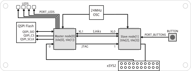
A board with a package with two nodes#
The following example describes a board with the XUF232-1024-FB167 package,
which contains two nodes, each comprising two xCORE tiles.
Note additional usb_tile declarations are provided to allow access to the USB PHYs.
Only one of these PHYs is connected to external package pins.
<?xml version="1.0" encoding="UTF-8"?>
<Network xmlns="http://www.xmos.com"
         xmlns:xsi="http://www.w3.org/2001/XMLSchema-instance"
         xsi:schemaLocation="http://www.xmos.com http://www.xmos.com">
  <Type>Board</Type>
  <Name>XUF232-1024-FB167-C40 Bringup</Name>

  <Declarations>
    <Declaration>tileref tile[4]</Declaration>
    <Declaration>tileref usb_tile[2]</Declaration>
  </Declarations>

  <Packages>
    <Package id="0" Type="XS2-UFnA-1024-FB167">
      <Nodes>
        <Node Id="0" InPackageId="0" Type="XS2-L16A-512" SystemFrequency="500MHz" OscillatorSrc="1">
          <Boot>
            <Source Location="bootFlash0"/>
            <Bootee NodeId="2"/>
          </Boot>
          <Tile Number="0" Reference="tile[0]">
            <Port Location="XS1_PORT_1B" Name="PORT_SQI_CS_0"/>
            <Port Location="XS1_PORT_1C" Name="PORT_SQI_SCLK_0"/>
            <Port Location="XS1_PORT_4B" Name="PORT_SQI_SIO_0"/>
          </Tile>
          <Tile Number="1" Reference="tile[1]"/>
        </Node>
        <Node Id="2" InPackageId="2" Type="XS2-L16A-512" SystemFrequency="500MHz" OscillatorSrc="3">
          <Boot>
            <Source Location="LINK" BootMode="4"/>
          </Boot>
          <Tile Number="0" Reference="tile[2]"/>
          <Tile Number="1" Reference="tile[3]"/>
        </Node>
        <Node Id="1" InPackageId="1" Type="periph:XS1-SU" Reference="usb_tile[0]">
        </Node>
        <Node Id="3" InPackageId="3" Type="periph:XS1-SU" Reference="usb_tile[1]">
        </Node>
      </Nodes>
      <Links>
        <Link Encoding="5wire" Delays="3clk">
          <LinkEndpoint NodeId="0" Link="7"/>
          <LinkEndpoint NodeId="2" Link="0"/>
        </Link>
        <Link Encoding="5wire" Delays="3clk">
          <LinkEndpoint NodeId="0" Link="4"/>
          <LinkEndpoint NodeId="2" Link="3"/>
        </Link>
        <Link Encoding="5wire" Delays="3clk">
          <LinkEndpoint NodeId="0" Link="6"/>
          <LinkEndpoint NodeId="2" Link="1"/>
        </Link>
        <Link Encoding="5wire" Delays="3clk">
          <LinkEndpoint NodeId="0" Link="5"/>
          <LinkEndpoint NodeId="2" Link="2"/>
        </Link>
        <Link Encoding="5wire">
          <LinkEndpoint NodeId="0" Link="8" Delays="52clk,52clk"/>
          <LinkEndpoint NodeId="1" Link="XL0" Delays="1clk,1clk"/>
        </Link>
        <Link Encoding="5wire">
          <LinkEndpoint NodeId="2" Link="8" Delays="52clk,52clk"/>
          <LinkEndpoint NodeId="3" Link="XL0" Delays="1clk,1clk"/>
        </Link>
      </Links>
    </Package>
  </Packages>

  <ExternalDevices>
    <Device NodeId="0" Tile="0" Class="SQIFlash" Name="bootFlash0" Type="S25LQ016B" PageSize="256" SectorSize="4096" NumPages="8192">
      <Attribute Name="PORT_SQI_CS" Value="PORT_SQI_CS_0"/>
      <Attribute Name="PORT_SQI_SCLK" Value="PORT_SQI_SCLK_0"/>
      <Attribute Name="PORT_SQI_SIO" Value="PORT_SQI_SIO_0"/>
    </Device>
  </ExternalDevices>

  <JTAGChain>
    <JTAGDevice NodeId="0"/>
    <JTAGDevice NodeId="2"/>
  </JTAGChain>

</Network>