The XVF3800 contains a control interface that enables users to configure the operation
of the device and to set and read parameter data.
In v3.2.1, a sample host application, xvf_host (Linux, macOS, Raspberry Pi OS)
or xvf_host.exe (Windows), is provided which can be used to connect to the control interface
on the XVF3800. Please contact XMOS for information on using these tools on other host platforms.
Before using the host application, the host and hardware must be configured as described in Setting up the hardware.
The sample xvf_host application can be found in the binary release package in the subdirectory
host_v<version>/<platform>. The supported platforms are linux_x86_64, mac_x86_64, mac_amr64, rpi and win32.
This whole directory needs to be transferred to the host computer. It can be placed in
any convenient location. This directory should contain the following files:
.├── (lib)command_map.(so/dll/dylib) # All platforms├── libdevice_i2c.so # RPi only├── libdevice_spi.so # RPi only├── dfu_cmds.yaml # RPi only├── transport_config.yaml # RPi only├── (lib)device_usb.(so/dll/dylib) # All platforms├── libusb-1.0.0.dylib # Mac_x86_64 and Mac_arm64 only├── xvf_dfu # RPi only└── xvf_host(.exe) # All platforms
To verify the xvf_host application is installed, change to the directory and run the application
as per the examples below, on Windows:
xvf_host.exe --help
on Linux, macOS and Raspberry Pi OS, the appropriate permissions must be set first:
sudo chmod +x xvf_hostsudo ./xvf_host --help
Users may find it convenient to store the host tools in a directory such as ~/bin
and add this to the PATH environment variable
so that the tools can be invoked from any directory. This can be done on Windows with the “Edit system environment variables” GUI,
or on the other platforms with the shell command:
PATH=~/bin:$PATH
Note
In the rest of this document when using the xvf_host app in the code examples, the command is written as (sudo)xvf_host(.exe).
The .exe extension is only required on Windows.
The sudo command is only required on Linux, macOS and Raspberry Pi OS if the user does not have the necessary permissions to access the device.
On these platforms it may be necessary to use ./ before the command if the directory containing the xvf_host app is not in the PATH.
When connecting an XVF3800 device to a Windows host, the Control and DFU interfaces should be listed under the Universal Serial Bus devices section in the Device Manager,
as shown below:
Fig. 16 USB interfaces in Device Manager on Windows#
If this is not the case, it may be necessary to uninstall the existing drivers. This can be done by following the steps below:
open the Device Manager on Windows
find the device, which may be located under libusb-win32 devices
right-click on the device
select Uninstall device
check the box to delete the driver software for this device
click Uninstall
Note
If the interface continues to appear in its original location, it may be necessary to perform these steps multiple times, suggesting that the drivers have been installed on multiple occasions.
See the picture below for an example when XMOS Control (Interface 3) is listed under libusb-win32 Devices:
Fig. 17 Uninstalling the driver in Device Manager on Windows#
To use the host application, login to the host computer – either directly,
via a VNC connection, or by ssh – to open a terminal command line.
Change to the directory containing xvf_host(.exe). If the host tools have been added to the path as
above this step is not needed.
The xvf_host device control application is run from the command line.
To check connection to the XVF3800, any command can be given; for example, the command
(sudo)xvf_host(.exe) --use <protocol> VERSION
where <protocol> can be i2c, spi or usb depending on the interface used in the
specific firmware. The default control protocol is USB.
This command should return “3 2 1”.
Note
The host application has no mechanism to select between multiple VocalFusion/XVF devices.
Using it with more than one XVF3800 device or with different VocalFusion/XVF devices connected at the same time may result in undefined behaviour.
The XVF3800 supports arbitrary microphone geometries which can be specified in configuration files.
Two default configurations are included in the binary release package that are aligned to the geometries supported on the XK-VOICE-SQ66 development kit.
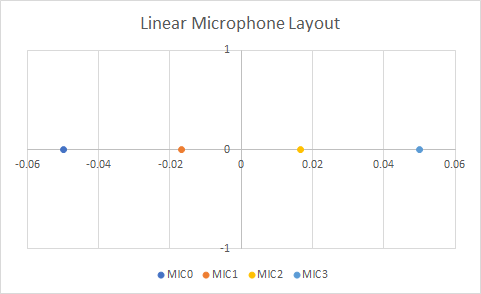
The linear configuration (-lin) comprises 4 microphones in a linear array, spaced 33mm apart, as shown below:
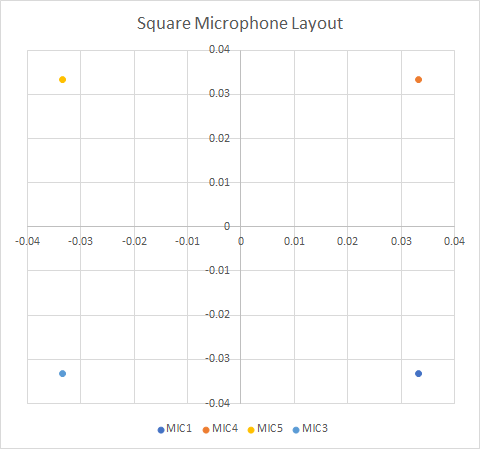
The square configuration (-sqr) uses a 4 microphone array with a 66mm distance along each side as shown below.
Note
These configurations are selected by a multiplexer on the XK-VOICE-SQ66 development kit when the device boots. They have to be configured as part of the firmware build and cannot be changed in operation.
The microphone numbers in the diagrams above correspond to the labels on the XK-VOICE-SQ66 development kit board.
In the firmware configuration these microphones are mapped to 4 microphone indexes: MIC[0..3] which are used
in the firmware and when using xvf_host. The mapping of the logical indexes and the physical microphones on the XK-VOICE-SQ66 development kit is shown in the table below:
Beam forming subsystem and Direction of Arrival indicator#
As described in XVF3800 datasheet, the system uses a set of beams to focus on speakers and
reduce unwanted sounds and reverberation in the output signal. The XVF3800 uses a free running beam
that scans the environment, identifies likely speakers and switches one of the two focused beams to that direction.
In normal operation the audio pipeline automatically selects the best signal to output.
It is possible to read back the direction that the beams are currently pointing.
This is done with the xvf_host command AEC_AZIMUTH_VALUES. The output of the command contains 4 values:
Focused beam 1
Focused beam 2
Free running beam
Auto selected beam
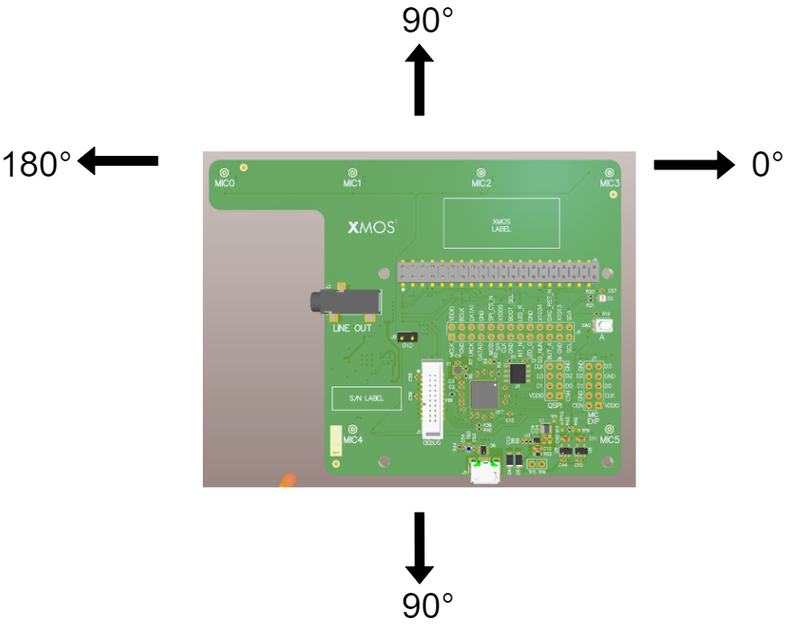
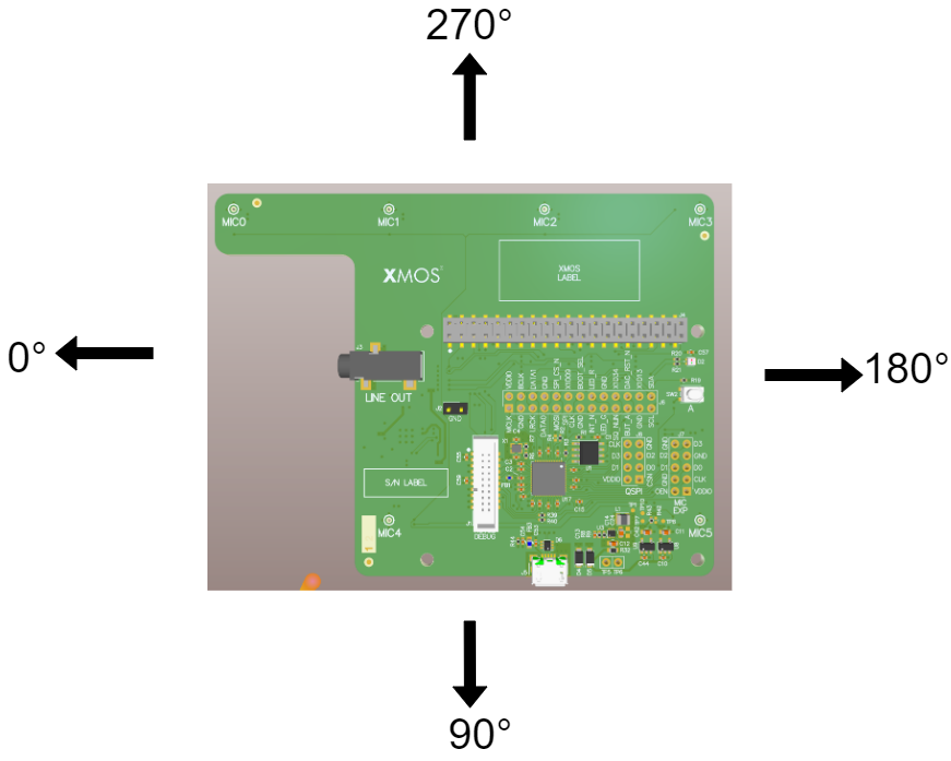
Each value is the azimuth angle of the corresponding beam, provided in both radians and degrees. The coordinate system used
depends on the hardware configuration. The diagrams below show the azimuth angles relative to the XK-VOICE-SQ66 development kit in the two default
configurations.
Fig. 18 Azimuth angle in linear configuration (note - 0 to 180 degrees only)#
During post-processing the speech energy (spenergy) is also calculated for each of the 4 beams. This value indicates whether
speech is present in the beam as well as the amplitude. Non-zero spenergy means that the beam probably contains speech.
Higher values indicate louder or closer speech, however noise, echo and reverb can cause the energy level to decrease.
These 4 floating point values can be read directly using the xvf_host command AEC_SPENERGY_VALUES. The 4 values map to the
beams in the same manner described for AEC_AZIMUTH_VALUES.
For situations where the speaker placements are known and will not change, the focused beams, numbered 0 and 1, can also be fixed in a specific direction.
The user can configure the azimuth and elevation angles of each beam.
Note
When using fixed mode, both focused beams must be fixed. It is not possible to fix only one.
To manage the beams in fixed mode the following commands are used:
AEC_FIXEDBEAMSAZIMUTH_VALUES: writes and reads back the azimuth values in radians for the beams in fixed mode.
AEC_FIXEDBEAMSELEVATION_VALUES: writes and reads back the elevation angles in radians for the beams in fixed mode.
AEC_FIXEDBEAMSONOFF: enables and disables the fixed focused beam mode.
AEC_FIXEDBEAMNOISETHR: writes and read back the threshold value for updating the noise canceller when fixed beam mode is enabled. A higher value indicates that the noise canceller may update when the free running beam is close to the fixed beam. A lower value indicates that the noise canceller may update when the free running beam is further away from the focused beam.
AEC_FIXEDBEAMSGATING: enables or disables gating on the fixed beams. With gating, fixed beams with a low speech energy will be muted. In addition, only one fixed beam will be active at a time; if both report a high enough speech energy, the one with the lower energy will be muted.
AEC_SPENERGY_VALUES: this is the same command used for the non-fixed beams, and four values are reported. If fixed focused beam mode is enabled by AEC_FIXEDBEAMSONOFF, the first two values are the speech energies of the fixed beams.
Note
Since the azimuth angle provided by the DoA function is dependent on the measurements of the acoustic path, the values reported by AEC_AZIMUTH_VALUES might not precisely match the fixed beam azimuth value.
Using azimuth data For Direction of Arrival indication#
The auto selection algorithm will switch between beams rapidly in some circumstances. The two focused beams
update relatively slowly, but the free running beam is designed to be sensitive so that it can rapidly pick
up the speech signal for a new talker entering the soundscape. As a result it can also pick up any noise signals present.
To provide maximum flexibility to system designers, the XVF3800 provides raw azimuth data which can be used as required.
XVF3800 also computes an additional azimuth value which combines speech energy and azimuths to provide a single value
which indicates the direction and presence of a speaker. This value can be read using the command AUDIO_MGR_SELECTED_AZIMUTHS.
The command returns 2 values, the first of which is the processed azimuth which will be NAN if there is no speech, otherwise
it will be the azimuth of the current speaker. The second is the current azimuth of the auto select beam.
A script, doa_plot.py, is included in the source release bundle. It uses the host app to visualise the current azimuths in real time. The
script can be called using the xvf_tools.py which is located in sources. Run the following command:
python3 xvf_tools.py doa_plot --command-help
for usage instructions. This command requires a positional argument with the path to the xvf_host binary, and a few optional arguments, for example --protocol to select the correct communication protocol.
The xvf_host tool allows the configuration of the XK-VOICE-SQ66 development kit to be changed during operations. The following examples illustrate some common operations.
By default, the left (first) channel of the device’s output is the processed output from the XVF3800’s AEC and beamforming stage,
while the right (second) channel is the raw input from one of the microphones after amplification.
This selection provides a good comparison between the raw and processed audio.
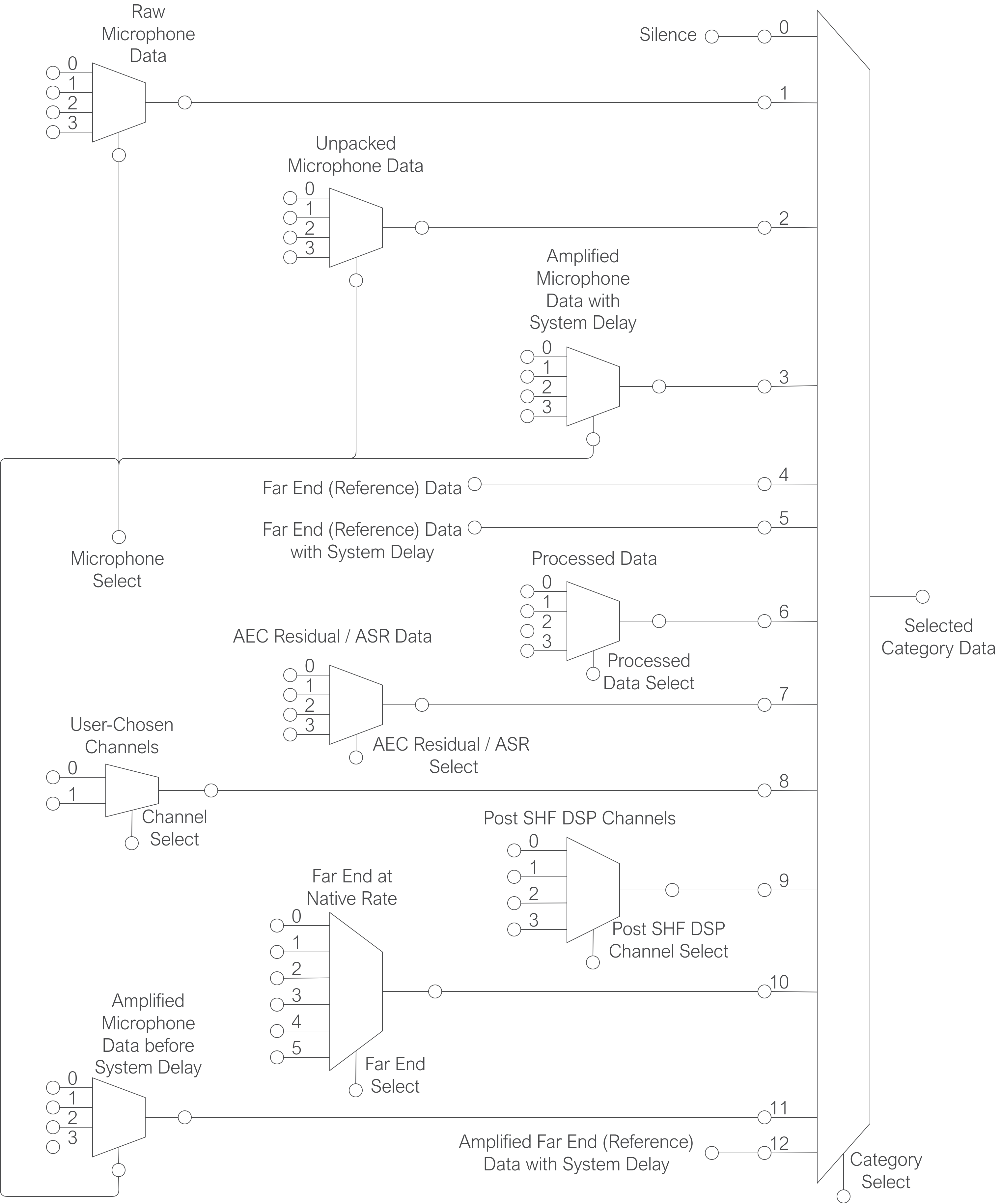
The selected outputs may be changed by using the AUDIO_MGR_OP_L and AUDIO_MGR_OP_R commands.
These commands each take two integers defining the mux routing settings, described as a pair of (category, source) values.
The available categories and sources are as detailed in Table 26.
0: Silence. This is the default setting for the right channel output.
1: Raw microphone data - before amplification
0,1,2,3: Specific microphones accessed by index, no system delay applied.
2: Unpacked microphone data
0,1,2,3: Unpacked microphone signals. If using packed input, access packed microphone data though this category. This data is undefined when not using packed input.
3: Amplified microphone data with system delay
0,1,2,3: Specific microphones accessed by index. This category provides the microphone signal passed to the SHF logical cores for processing.
4: Far end (reference) data
0: Far end data received over I2S, post sample rate conversion to 16 kHz if required.
5: Far end (reference) data with system delay
0: Far end data received over I2S, post sample rate conversion to 16 kHz if required, and with system delay applied.
6: Processed data
0,1: Slow-moving post-processed beamformed outputs, 2: Fast-moving post-processed beamformed output, 3: The “auto-select” beam; chooses the best of the previous three beams as an output, recommended option for selecting the beamformed outputs
7: AEC residual / ASR data
0,1,2,3: AEC residuals for the specified microphone, or ASR ouput for the specified beam.
8: User chosen channels
0,1: These currently copy the auto-select beam (category 6, source 3) and are the default setting for the left channel output.
9: Post SHF DSP channels
0,1,2,3: All output channels from user post SHF DSP.
10: Far end at native rate
0,1,2,3,4,5: Data passed from I2S logical core to Audio Manager logical core. All sources carry useful data if the external interface rate is 48 kHz. Only sources 0 and 1 carry useful data if the external interface rate is 16 kHz. See the Data Plane Detailed Design section in the Programming Guide for information on the interface between these two logical cores.
11: Amplified microphone data before system delay
0,1,2,3: Specific microphones accessed by index.
12: Amplified far end (reference) with system delay
0: Far end data received over I2S, post sample rate conversion to 16 kHz if required, and with a configurable fixed gain and system delay applied. This category provides the reference signal passed to the SHF logical cores for processing.
Fig. 20 shows the available categories and sources.
Inputs to the category multiplexer that have no preliminary multiplexer only support a single source.
For example, to set the left output to the 4th raw microphone signal (without gain applied), issue the command:
(sudo)xvf_host(.exe) AUDIO_MGR_OP_L 1 3
This will set the left channel to output the 4th (0-indexed) microphone signal of the 4 present.
To reset this channel back to its default value, issue:
(sudo)xvf_host(.exe) AUDIO_MGR_OP_L 8 0
to set the channel to the postprocessed auto-selected output beam.
Similarly, the right channel may be set to any desired category/source; to reset to its default value, issue: