Modifying the Software#
Adding a Control Command#
The XVF3800 software allows for easily extensible control. Each time the firmware is built, the command definition YAML files are parsed and the firmware hooks and enums are updated automatically. See Working With The Build System for how to build the XVF3800 firmware.
The command definition files can be found in sources/app_xvf3800/autogeneration/yaml_files/Control_commands.
There is a file for each control servicer within the firmware.
The control servicers are:
aec_cmds.yaml- This is where high level voice-DSP parameters are accessed as well as AEC information. The voice-DSP is not modifiable other than the published API. It is not expected that this file will need to be modified.application_cmds.yaml- This is where build information is accessed and some test features. The application servicer does not directly connect to any peripherals, however commands requiring internal storage or calling a user API may be added here.audio_cmds.yaml- This is where high-level aspects of the audio framework including SRC, packing, I2S and user-DSP are accessed. If extending the DSP capabilities of the design it is likely that commands may be added here, for example to control user-DSP. See Adding Custom Digital Signal Processing. Note that two tasks are controlled by this servicer (Audio Manager and I2S) with the I2S task being accessed via a shared-memory structure.dfu_cmds.yaml- This is where DFU messages are handled and processed. It is not expected that this file will need to be modified. This servicer is only used in the INT device.hid_task_cmds.yaml- This is where internal messages to send HID IN events are handled. It is not expected that this file will need to be modified. This servicer is only used in the UA device.io_config_cmds.yaml- This is where GPIO parameters are accessed. Commands are already provided for manipulating many aspects of these pins, although any custom requirements involving GPIO access may be added here.io_expander_cmds.yaml- This is where internal messages to control the IO expander GPO’s are handled. It is not expected that this file will need to be modified. This servicer is only used in the builds with the IO expander enabled.pll_cmds.yaml- This is where PLL information is accessed. Generation of the MCLK signal uses the PLL.pp_cmds.yaml- This is where high level voice-DSP parameters are accessed as well as post processing information. The voice-DSP is not modifiable other than the published API. It is not expected that this file will need to be modified.shf_aec_cmds.yaml- This is where low-level voice-DSP parameters are accessed. The voice-DSP is not modifiable other than the published API. This file is auto-generated and should not be modified.shf_pp_cmds.yaml- This is where low-level voice-DSP parameters are accessed. The voice-DSP is not modifiable other than the published API. This file is auto-generated and should not be modified.usb_buffer_cmds.yaml- This is where USB information and parameters are accessed. It only applies to UA configurations.
Adding a new control command#
This process is illustrated by adding a simple read/write parameter via application_cmds.yaml.
As an example of how to extend this to controlling IO, see the FAR_END_DSP_ENABLE parameter contained in audio_cmds.yaml.
First, add a command to the YAML file. The valid types that can be used for command parameters are as follows:
TYPE_INT32
TYPE_UINT32
TYPE_INT16
TYPE_UINT16
TYPE_INT8
TYPE_UINT8
TYPE_CHAR
TYPE_FLOAT
TYPE_RADIANS
Any number of these parameters may be defined in a control command, up to the total maximum command size of 64 bytes. Commands attributable to the pp_cmds servicer are exceptions; these are limited to 20 bytes.
The following access permissions may be assigned to parameters:
CMD_READ_ONLY
CMD_WRITE_ONLY
CMD_READ_WRITE
For write commands, a range must be provided for each value. If no value range is specified for such commands, the firmware code will fail to compile. The ranges must be listed in the value_ranges array and must follow one of the two formats:
list of intervals - each interval is listed using the syntax [A .. B]
the syntax is the same for both integers and float values
multiple intervals can be specified, for example [0 .. 5, 10 .. 15]
all the intervals must be closed, meaning that they include all the limit points
if only one value is valid, the range can be specified as [E .. E]
any value is valid - this is declared using the word any and the range depends on the maximum and minimum values of the specific type. For example, TYPE_UINT8 can have values from 0 to 255.
An example of a command with two arguments, where the first requires a list of intervals and the second accepts any value, is shown below:
value_ranges:
    - value0: [0 .. 5, 10 .. 15]
    - value1: any
Note
The host control application performs range checking before sending the control command to the device and it returns an error if any argument value is out of range.
An example of adding a command to application_cmds.yaml is shown below.
The position in the list at which the command is added is not important so long as it is in the appropriate section:
- cmd: MY_INTERNAL_REGISTER
  number_of_values: 1
  type: CMD_READ_WRITE
  help: A simple example of setting / getting a variable in the firmware
  value_type: TYPE_UINT32
Next, in the appropriate servicer C file, add the handlers for the command.
In this case we are adding the following code to sources/modules/fwk_xvf/modules/xvf/src/control_plane/application_servicer.c:
// Global variable to get or set
uint32_t my_var = 0;
In the function control_ret_t application_servicer_read_cmd() add the following case. Note the pre-pending of the resource ID to the command name:
case APPLICATION_SERVICER_RESID_MY_INTERNAL_REGISTER:
    memcpy(payload, &my_var, sizeof(my_var));
    break;
In the function control_ret_t application_servicer_write_cmd() add the following case:
case APPLICATION_SERVICER_RESID_MY_INTERNAL_REGISTER:
    memcpy(&my_var, payload, sizeof(my_var));
    break;
Next, build the firmware and host app; see Working With The Build System for instructions on this. Test the new command:
(sudo) xvf_host(.exe) MY_INTERNAL_REGISTER
0
(sudo) xvf_host(.exe) MY_INTERNAL_REGISTER 1066
(sudo) xvf_host(.exe) MY_INTERNAL_REGISTER
1066
Adding Custom Digital Signal Processing#
The XVF3800 supports the addition of custom DSP at three locations in the signal path. These points are:
Far-end reference signal DSP within the DAC
Far-end reference signal DSP within the XVF3800 firmware
Post-processing of the voice signal within the XVF3800 firmware after it exits the voice pipeline.
I2S Usage#
Understanding the two options for far-end reference signal DSP requires knowledge of how the XVF3800 uses the I2S signals. The purpose of each signal depends on the device configuration as shown in Table 39.
Signal |
Integrated Device (INT) |
USB Accessory (UA) |
|---|---|---|
I2S_DATA0 |
Input from host |
Output to DAC |
I2S_DATA1 |
Output to host |
Optional input from DAC |
I2S_DATA2 |
Optional output to DAC |
Not used |
Custom DSP Within the DAC#
Some Digital to Analogue Converters include optional DSP with the ability to transmit the altered signal before conversion via I2S and after conversion to an amplifier or loudspeaker. For designs using such a DAC and receiving the reference audio via USB, the XVF3800 UA configuration includes an option to accept a processed far-end reference signal over an I2S interface.
To enable this option, use the host control application to set the I2S_DAC_DSP_ENABLE control to 1 or modify the default value of the I2S_DAC_DSP_ENABLE control to 1. Information about using the host control application appears in the Using the Host Application section of the XVF3800 User Guide. Information about modifying the default value of a control parameter appears in the Changing Default Parameter Values section of the XVF3800 User Guide.
Custom DSP Within the XVF3800 Firmware#
Customer Far-End Reference DSP#
Custom DSP between the far-end (reference) input and the start of the far-field voice pipeline allows additional processing of the far-end signal, for instance correcting speaker/amplifier imperfections to ensure optimum AEC performance. The voice pipeline, and optionally the DAC via I2S, receives a copy of the processed far-end signal.
Fig. 70 shows the audio paths for the far-end DSP as well as where up/down-sampling may occur.
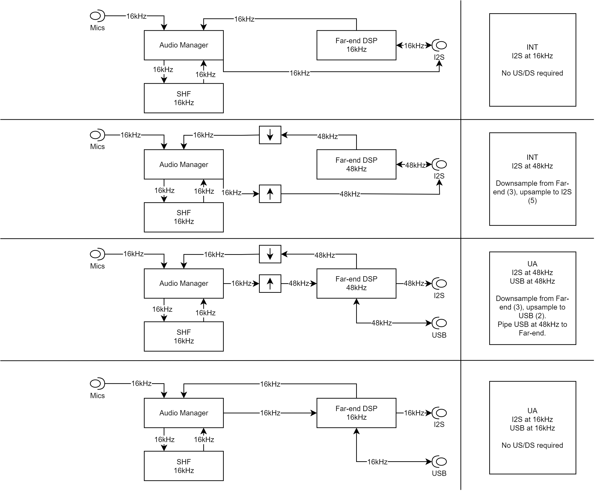
Fig. 70 Audio paths for far-end DSP and where up/down-sampling may occur in the XVF3800.#
Custom Voice Post-Processing DSP#
While the standard voice processing offers a wide range of typically needed functions such as AGC, high-pass filtering and automatic beam selection, some users may wish to augment these functions. Custom DSP post-processing occurs immediately after the processed microphone signal leaves the voice pipeline and before the XVF3800 sends it to the host.
Common Aspects to Custom DSP Within the XVF3800 Firmware#
Both DSP hooks provide an API in which processing of a single sample occurs for each function call. This approach reduces latency (block based algorithms introduce a minimum latency of the block size) and simplifies integration into the main firmware framework. The lib_xcore_math library provides various DSP functions including FIR filters and Biquad IIR filters. An example of the latter is given further on.
Note
Integration of user DSP consumes processing cycles from the processor. These are limited according to the build and host sample rates used. Please see Meeting timing for details.
The API for the firmware-based custom DSP functions is transcluded below from sources/modules/fwk_xvf/modules/xvf/src/user_interfaces/user_dsp.h:
// Copyright 2022-2023 XMOS LIMITED.
// This Software is subject to the terms of the XCORE VocalFusion Licence.

#ifndef __USER_DSP_H_
#define __USER_DSP_H_

#include "aec_cmds.h"
#include "shf_wrapper.h"
#include <stdint.h>

/// There is a timing limit on the time spent in these functions. Please use the
/// minimum idle time control commands in conjunction with the TEST_CORE_BURN command to
/// characterise the amount of cycles available.
/// The far_end_dsp function is called from I2S and so check min_idle time for that task
/// The far_end_dsp function is called from Audio so check min_idle time for that task


/// @brief callback to pre-process one sample of the far end before outputting to DAC/SHF DSP input
/// Note that this callback runs at the I2S sample rate.
/// @param far_end_sample      input and output (sample is processed in place)
/// @param far_end_dsp_enable  Set to 1 to enable, 0 to disable. This is handled by the user.
void far_end_dsp(int32_t far_end_samples[BECLEAR_NUMBER_OF_FAR], bool far_end_dsp_enable);

/// Struct passed to post_shf_dsp which contains all the information that is available
/// for additional post-processing.
typedef struct {
    /// Pointer to array containing the BECLEAR_NUMBER_OF_OUTPUTS processed microphone channels.
    int32_t* post_shf_processed_mic_samples;

    /// BECLEAR_NUMBER_OF_MICS channels containing the microphones after AEC before post-processing.
    int32_t* aec_residuals;

    /// Pointer to array of BECLEAR_NUMBER_OF_OUTPUTS azimuths, each element is the azimuth for the
    /// post_shf_processed_mic_samples of the same index. It can be NULL if azimuths have not been
    /// calculated.
    float* azimuths;

    /// The spenergy (speech energy) for each beam in post_shf_processed_mic_samples. If the spenergy
    /// is non-zero then it contains energy that is likely speech. The value will be higher for louder
    /// or closer voices, noise and distortion will cause the speech energy to decrease. This points
    /// to an array of size BECLEAR_NUMBER_OF_OUTPUTS where each value corresponds to the beam of the
    /// same index. It can be NULL if spenergy has not been calculated.
    float* spenergy;

    /// Output of xmos algorithm to determine the direction of voice, NAN if no voice detected
    float direction_of_voice;
} user_dsp_post_shf_input_t;

/// @brief callback to post-process one sample of audio after the SHF voice DSP stage
/// Note that this callback runs at the SHF sample rate.
/// @param out Array to fill with the output of this function.
/// @param input See user_dsp_post_shf_input_t comments for details.
void post_shf_dsp(int32_t out[BECLEAR_NUMBER_OF_OUTPUTS],
                  user_dsp_post_shf_input_t* input);

#define USER_DSP_NUM_OUTPUT_CHANNELS 2

/// @brief called immediately after post_shf_dsp and will be used to determine the
/// channels that MUX_USER_CHOSEN_CHANNELS will consist of. It also sets the azimuth
/// of each chosen channel so that it can be requested via control command.
///
/// @param[in,out] out_idx 2 chosen channels from `out` which were written by
///    the function `post_shf_dsp`. Before being passed to beam_selection,
///    out_idx will be populated by the suggested indices.
/// @param[out] out_azimuths azimuths of the two channels that have been
///    selected. Most likely a copy of the correct input from above.
void beam_selection(uint8_t out_idx[USER_DSP_NUM_OUTPUT_CHANNELS],
                    float out_azimuths[USER_DSP_NUM_OUTPUT_CHANNELS]);

#endif
Meeting Timing#
When adding custom DSP, it is important to check timing. It is not sufficient just to check that audio is playing cleanly because the available cycles within the XVF3800 varies significantly depending on operation and will increase under certain conditions. A comprehensive method for checking worst case timing is included and can be found in the Testing the Software section of the Programming Guide.
Adding Control to Custom DSP#
In some cases it may be desirable to add a new control command to allow the host application to enable/disable or adjust the custom DSP. The steps in Adding a Control Command show how to add controls to the firmware and the below examples include adding a control for each case.
For far-end reference DSP within the XVF3800 firmware, a built-in control named AUDIO_MGR_FAR_END_DSP_ENABLE has already been provided. It is possible to add further controls if needed.
Far-End Reference DSP#
Both far-end reference DSP locations offer the opportunity to add processing between the host audio signal and the DAC output. If adding non-linear processing (eg. bass-enhancement, dynamic-range compression), placing that processing in one of these locations will avoid degradation in AEC performance. If it is located somewhere else in the system, this DSP may significantly degrade AEC performance due to the far-end reference given to the voice pipeline differing from the signal played through the loudspeaker. The remainder of this section will discuss far-end reference DSP placed within the XVF3800 firmware.
The rate of the DSP is the host interface rate. For example, if I2S runs at 48 kHz, then the far-end DSP also runs at 48 kHz. The samples will not be sent to the voice pipeline until after the far-end DSP has occurred and will be down-sampled if required.
Because the far-end DSP block will add delay to the voice pipeline reference signal, it is essential that any delay added is not so large that the direct path (loudspeaker to microphone) of the far-end signal arriving at the microphones gets to the voice pipeline before the processed far-end signal does. This non-causal relationship will cause a rapid degradation in AEC performance. For more information on this topic, including how to measure this effect, see the Tuning the Application section of the XVF3800 User Guide.
Depending on the external audio path and the type of processing applied (linear vs non-linear) it may be necessary to add an additional audio line. For example, an I2S connected system may need one audio line for the reference input, one audio line for the processed microphone output and an additional line for the processed far-end output to the DAC. Where the far-end audio source is USB, this additional audio line is not necessary since the processed far-end output will always be sent to the DAC pin.
The XVF3800 allows provision of a third I2S line for processed far-end output using the following steps:
Increase
appconfNUM_I2S_PINS_OUTinapp_conf.hfrom 1 to 2. This will enable PORT_I2S_DATA2 as an I2S output pin. The default is to set the second pin to output the post-processed far-end input with sample rate conversion disabled.Set
USE_FAR_END_DSPinfar_end_dsp.cto 1.Make sure the DAC input is connected to the processed far-end DSP signal.
Note
Far-end reference DSP is disabled by default in the standard build to avoid using extra memory and processing cycles.
In the USB build, the pin formerly used as the I2S input to the device is used by default as an I2S output to send the far-end signal to the DAC.
Therefore, for the USB build, it is usually sufficient to keep appconfNUM_I2S_PINS_OUT set to 1. By default, the processed far-end signal will be routed to this output.
However, the secondary I2S line may still be enabled with the above steps if desired.
In order to verify the effect of the DSP, you may wish to send the product of the far-end DSP directly to the DAC without any incident down- or up-sampling. The following commands ensure up-sampling is disabled and route far-end DSP signal to the output:
(sudo) xvf_host(.exe) AUDIO_MGR_OP_UPSAMPLE 0 0
(sudo) xvf_host(.exe) AUDIO_MGR_OP_ALL 10 0 10 2 10 4 10 1 10 3 10 5
A control command has already been provided which passes a boolean to the far_end_dsp() function, which allows the user to enable and disable the far-end DSP and verify its functionality. This may be controlled using:
(sudo) xvf_host(.exe) AUDIO_MGR_FAR_END_DSP_ENABLE 1
(sudo) xvf_host(.exe) AUDIO_MGR_FAR_END_DSP_ENABLE 0
Far-end reference example#
For example purposes, a three stage biquad filter has been implemented which boosts bass and treble by 6 dB and cuts mid-range by 6 dB. This filter produces a noticeable effect suitable for demonstration purposes and for verification that the far-end DSP is active. This example has coefficients that have been generated assuming a 48 kHz sample rate. They will not work properly at 16 kHz and will need to be re-calculated.
The code is shown below, transcluded from sources/app_xvf3800/src/user_dsp/far_end_dsp.c:
// Copyright 2022-2023 XMOS LIMITED.
// This Software is subject to the terms of the XCORE VocalFusion Licence.

#include "user_dsp.h"

#ifndef USE_FAR_END_DSP
    #define USE_FAR_END_DSP 0
#endif

#if USE_FAR_END_DSP
#include "xmath/xmath.h"

// Simple example DSP that processes far end using an EQ. Note the coeffs are correct for 48kHz only
// Each filter_biquad_s32_t can store (up to) 8 biquad filter sections
#define SECTION_COUNT   3

filter_biquad_s32_t filter[BECLEAR_NUMBER_OF_FAR] = {{
    // Number of biquad sections in this filter block
    .biquad_count = SECTION_COUNT,

    // Filter state, initialized to 0
    .state = {{0}},

    // Filter coefficients
    // Section 0: Frequency = 100 Hz, Q Factor = +1.2,  Gain = +6.0dB
    // Section 1: Frequency = 1000 Hz, Q Factor = +0.2, Gain = -6.0dB
    // Section 2: Frequency = 8000 Hz, Q Factor = +1.3, Gain = +6.0dB
    .coef = {
        { Q30(+1.00286226693868),  Q30(+0.86561763867029),  Q30(+1.58124059575259)},
        { Q30(-1.98608850422494),  Q30(-1.44869047773446),  Q30(-1.32398889950623)},
        { Q30(+0.98346660965693),  Q30(+0.59557353208939),  Q30(+0.56062804987035)},
        { Q30(+1.98614845462853),  Q30(+1.44869047773446),  Q30(+0.45958190453639)},
        { Q30(-0.98626892619203),  Q30(-0.46119117075968),  Q30(-0.27746165065311)}
        }
}};


void far_end_dsp(int32_t far_end_samples[BECLEAR_NUMBER_OF_FAR], bool far_end_dsp_enable)
{
    // See note in user_dsp.h and user documentation about timing constraints
    if(far_end_dsp_enable)
    {
        for(int channel = 0; channel < BECLEAR_NUMBER_OF_FAR; channel++)
        {
            far_end_samples[channel] >>= 1; // Simple 6db pre-attenuate to account for gain in filter
            far_end_samples[channel] = filter_biquad_s32(&filter[channel], far_end_samples[channel]);
        }
    } else {
        for(int channel = 0; channel < BECLEAR_NUMBER_OF_FAR; channel++)
        {
            far_end_samples[channel] >>= 1; // Simple 6db attenuate to account for filter gains to give similar apparent volume
        }
    }
}

#else

void far_end_dsp(int32_t far_end_samples[BECLEAR_NUMBER_OF_FAR], bool far_end_dsp_enable)
{
    // Do nothing - samples unmodified
}

#endif
Testing the effect on available cycles, we can see a modest drop from the three stage biquad of just 85 x 10 ns = 0.85 us. This small drop is due in part to the use of the Vector Processing Unit (VPU), which is highly efficient for signal processing purposes. Note that the idle time is not calculated until I2S runs:
(sudo) xvf_host(.exe) TEST_CORE_BURN 1
(sudo) xvf_host(.exe) I2S_MIN_IDLE_TIME
2083
aplay <short wav>
aplay <short wav>
aplay <short wav>
(sudo) xvf_host(.exe) I2S_MIN_IDLE_TIME
1245
(sudo) xvf_host(.exe) AUDIO_MGR_FAR_END_DSP_ENABLE 1
aplay <short wav>
aplay <short wav>
aplay <short wav>
(sudo) xvf_host(.exe) I2S_MIN_IDLE_TIME
1160
Voice Post-Processing DSP#
As the name suggests, this DSP hook allows the user to add any required DSP after the microphone signals have passed through the voice pipeline. The rate of the processing is always the rate of the voice pipeline (nominally 16 kHz). A number of audio signals are available including multiple output beams and AEC residuals which are the echo-cancelled only signals for each of the four microphones.
To allow more informed selection of the output beam, the Direction of Arrival (DoA) azimuths and the speech energy are also provided to allow custom logic to choose the desired signal.
Adding processing to this part of the chain will not affect the performance of the core voice pipeline. However, it will add to the total delay through the device from microphones to output interface.
Follow the same steps as per the Far-end reference example except when checking timing, please use AUDIO_MGR_MIN_IDLE_TIME instead of I2S_MIN_IDLE_TIME since the processing cycles are consumed from a different task. The Testing the Software section also provides detailed information on how to check timing.
Spatial output example#
An example is provided in post_shf_dsp.c which uses the DoA information to pan the auto select beam onto the left and right output channel.
This allows for a stereo output from the device giving audible indication of the location of the speaker.
This feature can be enabled using a macro named appconfSPATIAL and is enabled in build configs with the -spatial suffix.
These configs also configure the output multiplexer (mux) to play the left and right outputs back to the host correctly.
To get the best output from this example the macro LEFT_ANGLE_RADIANS may need to be updated so that the correct output is heard.
For linear microphone arrays this will either be 0 or M_PI depending on the microphone geometry.
After changing the software, it will need to be recompiled and flashed to the device.
Modifying Existing Functionality#
The XVF3800 provides the ability to customise the initialisation code for any connected hardware at firmware boot time.
During run-time, the GPIO pins may be modified via control commands from the host control application.
Initialisation typically involves setting GPO pins to control board level features such as LEDs and configuring I2C connected devices such as an IO expander, a DAC, or a digital amplifier.
The code for user hardware initialisation can be found in sources/app_xvf3800/src/user_config.
The main file to be modified is user_config.c which is shown below.
// Copyright 2022-2023 XMOS LIMITED.
// This Software is subject to the terms of the XCORE VocalFusion Licence.

#include "FreeRTOS.h"
#include "app_conf.h"
#include "user_config.h"
#include "io_config_servicer.h"
#include "dac3101.h"

// This file contains the user hardware configuration code. It uses the implementations in dac3101.h (EVK3800)
// and the lower level hardware implementations in dac_port.c

int user_init_hardware(device_control_t *device_control_gpio_ctx)
{
    int errors_encountered = 0;

    rtos_printf("user_init_hardware\n");

#if !defined(MIC_ARRAY_TYPE)
#error
#endif
#if MIC_ARRAY_TYPE == BECLEAR_LINEAR_ARRAY
    write_gpo_pin(device_control_gpio_ctx, GPO_SQ_nLIN_PIN, 0);
#elif MIC_ARRAY_TYPE == BECLEAR_CIRCULAR_ARRAY
    write_gpo_pin(device_control_gpio_ctx, GPO_SQ_nLIN_PIN, 1);
#else
    #error MIC_ARRAY_TYPE invalid
#endif

    // De-assert HOST INTERRUPT line
    write_gpo_pin(device_control_gpio_ctx, GPO_INT_N_PIN, 1); // No interrupt to host asserted when high

#if (appconfUSER_CONFIG_ENABLED == 1)
    // Reset the DAC
    dac3101_codec_reset(device_control_gpio_ctx);

    errors_encountered |= dac3101_init(appconfLRCLK_NOMINAL_HZ);
#endif

    // Test that we can turn on a LED by sending a command from this task to the GPO task
    // Note even though LEDs are active low, we have setup the LED pins in gpo_servicer to drive negaive logic
    for(int i = 0; i < 5; i++){
        write_gpo_pin(device_control_gpio_ctx, GPO_LED_GREEN_PIN, 1); // Turn the green LED on
        vTaskDelay(pdMS_TO_TICKS(100));
        write_gpo_pin(device_control_gpio_ctx, GPO_LED_GREEN_PIN, 0); // Turn the green LED off
        vTaskDelay(pdMS_TO_TICKS(100));
    }

    return errors_encountered;
}
This file is currently configured for the XK-VOICE-SQ66 development kit and its associated hardware set.
In this file we can see the following actions taken:
Setting of GPO output line on the XK-VOICE-SQ66 development kit to control the microphone array topology.
Setting of GPO output line to de-assert the host interrupt line.
Resetting of the DAC. See the next section Digital to Analogue Converter Configuration for details.
Configuring the DAC. See the next section Digital to Analogue Converter Configuration for details.
Flashing the green LED five times to show that booting of the XVF3800 is occurring.
Note
The control plane part of the XVF3800 firmware, responsible for servicing control commands from the host, will not start until the call to user_init_hardware() is complete. Any control commands issued by the host before initialisation is complete will not be serviced.
Digital to Analogue Converter Configuration#
Each DAC or digital amplifier selected will normally have its own set of registers that need to be configured.
There are two parts to the DAC configuration code.
The first is the abstraction layer responsible for providing the I2C, GPO, and wait functions.
These may need to be modified if the GPO responsible for resetting the DAC or the I2C register access methods needs to be altered.
This file can be seen below, transcluded from sources/app_xvf3800src/user_config/dac_port.c:
// Copyright 2022-2023 XMOS LIMITED.
// This Software is subject to the terms of the XCORE VocalFusion Licence.

// This file contains the implementations of the DAC configuration steps such as which registers to write with which values
// Note there are currently two implementations because in I2C slave we init the DAC pre-RTOS

/* FreeRTOS headers */
#include "FreeRTOS.h"

/* App headers */
#include "xcore/port.h"
#include "rtos_i2c_master.h" // Includes "i2c.h" too
#include "platform/driver_instances.h"
#include "io_config_servicer.h"
#include "user_config.h"
#include "dac3101.h"


void dac3101_wait(uint32_t wait_ms)
{
    vTaskDelay(pdMS_TO_TICKS(wait_ms));
}

#if (appconfUSER_CONFIG_ENABLED == 1) // Some builds use a specific control transport but DO NOT require setting up of DAC HW

int dac3101_reg_write(uint8_t reg, uint8_t val)
{
    rtos_i2c_master_t * i2c_master_ctx = get_i2c_master_ctx();
    i2c_regop_res_t ret = rtos_i2c_master_reg_write(i2c_master_ctx, DAC3101_I2C_DEVICE_ADDR, reg, val);

    if (ret == I2C_REGOP_SUCCESS) {
        return 0;
    } else {
        return -1;
    }
}


void dac3101_codec_reset(void * args)
{
    device_control_t *device_control_gpio_ctx = args;

    write_gpo_pin(device_control_gpio_ctx, GPO_DAC_RST_N_PIN, 0);
    dac3101_wait(1);  /* From DS - The hardware reset pin (RESET) must be pulled low for at least 10ns */
    write_gpo_pin(device_control_gpio_ctx, GPO_DAC_RST_N_PIN, 1);
    dac3101_wait(1); /* From DS - This initialization takes place within 1 ms after pulling the RESET signal high */
}
#endif
The second file, which specifies the sequence of GPO accesses and I2C register writes specific to the chosen DAC, can be found in sources/modules/fwk_xvf/modules/bsp/dac.
There are two files which may need to be modified: dac3101.h, which contains the defines and function prototypes, and dac3101.c, which contains the dac3101_init() function that is called from user_config.c and performs the sequence of operations required to configure the DAC.
These sources are not printed here for documentation brevity.
Note
Error detection is included and errors (non-zero return) will be reported back to the application if encountered.
General Purpose Input and Output Operation#
Several GPIO ports are provided by the XVF3800 to allow input and output capability.
These may be accessed from the firmware at startup via user_config.c or by the host application using GPO and GPI commands.
The XVF3800 ports contain a single direction register and therefore groups of pins on a single port are all either input or output.
The firmware provides functionality to address individual pins within a port.
GPI ports provide the capability to read the current state of pins, invert their logic, and capture an edge (event). GPO ports provide the ability to output a logic level, autonomously flash a 32b serial pattern, or provide a PWM signal suitable for dimming LEDs.
The initial configuration of the roles of each GPO pin can be found in the function init_gpo() in sources/modules/fwk_xvf/modules/xvf/src/control_plane/gpo_servicer.c.
This contains the GPO setup for the XVF3800 demonstration board including initial level and drive invert.
Drive invert can be useful for negative logic hardware such as LEDs connected between the 3v3 rail and the GPO pin.
Note
Because GPO pins support PWM, setting the duty to 100% or 0% is the same as setting a 1 or 0.
The write_gpo_pin() function hides this functionality by providing a simple logic write; however, the initialisation section in gpo_servicer.c initialises a PWM value of 0 or 100.
Additionally, the flash mask is set to 0xffffffff so that there is no flash sequence enabled.
Individual bit defines for the individual pins in the default firmware can be found in sources/app_xvf3800/src/app_conf.h.
Once the pin roles and initial values have been configured, they may be accessed using a simple API providing logic level access. An example is shown in the code listing in Modifying Existing Functionality which asserts GPO pins during the DAC setup.
Note
In the XVF3800 firmware, the GPI servicer is currently only defined on tile[1]; therefore, ports associated with tile[0] cannot be used as GPI pins without first modifying the firmware to instantiate a GPI servicer on tile[0]. Such a change will require significant alteration of the existing functionality. Consequently, it is not possible to easily use ports on tile[0] as GPI sources within the application. However, depending on desired functionality, it may be possible to use certain ports outside of the application layer, for example during boot as sense pins for a custom flash loader as described in the XMOS XTC Tools User Guide.
USB configuration#
In the XVF3800-UA device, several settings related to the USB interfaces can be configured.
The USB audio sample rate can be configured using the appropriate build configuration as described in the Building the Application section of the XVF3800 User Guide.
The remaining USB settings can be updated using the usb_param_values.yaml in sources/app_xvf3800/autogeneration/yaml_files/settings_and_defaults/.
This file contains additional configurable parameters used in the USB descriptors, such as vendor ID and product ID, and the default data bit depths of the input and output audio.
The full list of parameters and their default values are below:
VENDOR_ID: 0x20B1
PRODUCT_ID_IO_16KHZ: 0x4F01
PRODUCT_ID_IO_32KHZ: 0x0000
PRODUCT_ID_IO_48KHZ: 0x4F00
MANUFACTURER_STR: "XMOS"
PRODUCT_STR: "XVF3800 Voice Processor"
SERIAL_NUMBER_STR: "000000"
CONTROL_INTERFACE_STR: "XMOS Control"
HID_INTERFACE_STR: "XMOS HID"
DFU_FACTORY_INTERFACE_STR: "XMOS DFU Factory"
DFU_UPGRADE_INTERFACE_STR: "XMOS DFU Upgrade"
DEFAULT_BIT_DEPTH_IN: "16"
DEFAULT_BIT_DEPTH_OUT: "16"
Programmatically Rebooting the Device#
In both the XVF3800-UA and XVF3800-INT devices, the function
reboot_xvf3800(unsigned delay) is provided in tile_common.h to
facilitate rebooting the device from within the application. It is declared as
/// @brief reboot the package that called this function after delay ms
/// @param delay a count in ms that will wait until the reboot happens
void reboot_xvf3800(unsigned delay);
This will enable the watchdog timer and instruct it to operate after delay
milliseconds. The function will return when complete, but the reboot will have
been scheduled as requested. For more information on the operation of the
watchdog timer, see the datasheet for the relevant xcore.ai package.
The device may also be rebooted by use of the RST_N pin. Pulling this pin
low externally will force a hardware reboot of the device. For more information,
including the pin number of the RST_N pin on the relevant package, see the
Device Datasheet included in the XVF3800 documentation set.
Modifying the HID to GPIO mapping#
The init_hid_button_config and init_hid_led_config functions in sources/modules/fwk_xvf/modules/xvf/src/usb/control_plane/hid_init.c can be
modified to change the mapping between the HID buttons/LEDs and the GPIO buttons/LEDs. For more details about the HID design, refer to HID Interface design
Changing LED mapping#
By default, the code in init_hid_led_config maps the HID Off-Hook LED to the Green LED on the XK-VOICE-SQ66 development kit and the HID Mute LED to the Red LED on the XK-VOICE-SQ66 development kit.
    hid_led_config_t config = {.report_id = REPORT_ID_MISC_BUTTONS, .offset = LED_OFFHOOK_OFFSET, .gpo_source = GPO_SOURCE_EVK, .gpo_pin_index = EVK_LED_GREEN, .notify_hid_task = true, .trigger_hid_input_index = HOOKSWITCH_BUTTON, .led_mode=LED_MODE_STEADY};
    hid_led_config[OFFHOOK_LED] = config;
    hid_led_config_t config = {.report_id = REPORT_ID_MISC_BUTTONS, .offset = LED_MUTE_OFFSET, .gpo_source = GPO_SOURCE_EVK, .gpo_pin_index = EVK_LED_RED, .notify_hid_task = false, .trigger_hid_input_index = NO_HID_IN_TRIGGER, .led_mode=LED_MODE_STEADY};
    hid_led_config[MUTE_LED] = config;
This can be changed and any of the remaining HID LEDs, the Ring and Hold LED, can be mapped to the XK-VOICE-SQ66 development kit LEDs. To make the change, first make sure that the existing mapping is removed. For example, when mapping the Green LED to something else, make sure that the existing Off-Hook to Green LED mapping is removed. This is done by changing the gpo_source and gpo_pin_index to LED_GPO_UNMAPPED for the OffHook LED.
{
   hid_led_config_t config = {.report_id = REPORT_ID_MISC_BUTTONS, .offset = LED_OFFHOOK_OFFSET, .gpo_source = LED_GPO_UNMAPPED, .gpo_pin_index = LED_GPO_UNMAPPED, .notify_hid_task = true, .trigger_hid_input_index = HOOKSWITCH_BUTTON, .led_mode=LED_MODE_STEADY};
   hid_led_config[OFFHOOK_LED] = config;
}
Then, for the HID LED that needs to be mapped to the Green XK-VOICE-SQ66 development kit LED, set the .gpo_source as GPO_SOURCE_EVK and gpo_pin_index as EVK_LED_GREEN. For example, if mapping the Ring LED to the Green LED, change
{
   hid_led_config_t config = {.report_id = REPORT_ID_MISC_BUTTONS, .offset = LED_RING_OFFSET, .gpo_source = GPO_SOURCE_EVK, .gpo_pin_index = EVK_LED_GREEN, .notify_hid_task = true, .trigger_hid_input_index = NO_HID_IN_TRIGGER, .led_mode=LED_MODE_FAST_FLASH};
   hid_led_config[RING_LED] = config;
}
Note
This code change needs to be made for the code that is not in the #if (IO_EXPANDER_ENABLED) define block.
Modifying the HID to GPIO mapping for the IO expander build#
Similar to Modifying the HID to GPIO mapping the GPIO to HID events mapping can be changed by modifying the code in the init_hid_button_config and init_hid_led_config
functions in sources/modules/fwk_xvf/modules/xvf/src/usb/control_plane/hid_init.c. For the IO expander build (application_xvf3800_ua-io48-lin-io-exp), the code within #if (IO_EXPANDER_ENABLED)
needs to be modified.
The GPI button is defined by the gpi_source and gpi_pin_index fields in the hid_button_config_t structure. To change the GPI button mapped to a given HID button, change the
gpi_source and gpi_pin_index fields in the initialisation code for that button in the init_hid_button_config function.
The available GPI sources and pin indexes for every source are defined in sources/modules/fwk_xvf/modules/xvf/src/usb/control_plane/usb_hid.h
/// @brief Buttons sources. The EVK and the IO expander board
typedef enum
{
    GPI_SOURCE_EVK = 0,
    GPI_SOURCE_IO_EXP
}all_gpi_sources_t;

/// @brief Button indexes for the buttons on the EVK.
typedef enum
{
    EVK_BUTTON_INDEX = 0,
    TOTAL_EVK_BUTTONS
}all_evk_buttons_t;

/// @brief Button indexes for the buttons on the IO expander
typedef enum
{
    IO_EXP_MUTE_BUTTON_INDEX = 0,
    IO_EXP_VOL_UP_BUTTON_INDEX,
    IO_EXP_VOL_DN_BUTTON_INDEX,
    IO_EXP_ACTION_BUTTON_INDEX,
    TOTAL_IO_EXP_BUTTONS
}all_io_exp_buttons_t;
The GPO LED is defined by the gpo_source and gpo_pin_index fields in the hid_led_config_t structure. To change the GPO LED mapped to a given HID LED, change the
gpo_source and gpo_pin_index fields in the initialisation code for that LED in init_hid_led_config function.
The available GPO sources and pin indexes for every source are defined in sources/modules/fwk_xvf/modules/xvf/src/usb/control_plane/usb_hid.h
/// @brief LED sources. The EVK and the IO expander board
typedef enum
{
    GPO_SOURCE_EVK = 0,
    GPO_SOURCE_IO_EXP
}all_gpo_sources_t;

/// @brief LEDs on the EVK board
typedef enum
{
    EVK_LED_GREEN,
    EVK_LED_RED,
    TOTAL_EVK_LEDS
}all_evk_leds_t;

/// @brief LEDs on the IO Expander board
typedef enum
{
    IO_EXP_PCAL6416A_LED, // Red LED on the IO expander
    IO_EXP_IS31FL3193_RGB_LED,  // IS31FL3193 RGB LED on the IO expander
    TOTAL_IO_EXP_LEDS
}all_io_exp_leds_t;
Adding a different I2C Expander#
The HID + I2C expander design described in System Design mentions the io_expander_task that is
responsible for responding to buttons and driving LEDs on the I2C expander.
The existing io_expander_task is written for supporting the PCAL6416A I2C expander
and requires modifications when supporting a different I2C expander.
In addition, the definitions for the buttons and LEDs supported on the I2C expander that get exposed to the HID tasks will need to be modified. Section Defining available GPIO on the IO expander describes this,
followed by Modifying the IO expander task which describes the changes required to the io_expander_task for supporting a different I2C exapnder.
Defining available GPIO on the IO expander#
The (gpi_source, gpi_pin_index) fields in the hid_button_config_t structure and the (gpo_source, gpo_pin_index) fields
in the hid_led_config_t structure define the GPIO buttons/LEDs that are mapped to HID buttons/LEDs.
The available GPIO sources and the buttons/LEDs supported per source are defined as enums in sources/modules/fwk_xvf/modules/xvf/src/usb/control_plane/usb_hid.h.
/// @brief Buttons sources. The EVK and the IO expander board
typedef enum
{
    GPI_SOURCE_EVK = 0,
    GPI_SOURCE_IO_EXP
}all_gpi_sources_t;

/// @brief Button indexes for the buttons on the EVK.
typedef enum
{
    EVK_BUTTON_INDEX = 0,
    TOTAL_EVK_BUTTONS
}all_evk_buttons_t;

/// @brief Button indexes for the buttons on the IO expander
typedef enum
{
    IO_EXP_MUTE_BUTTON_INDEX = 0,
    IO_EXP_VOL_UP_BUTTON_INDEX,
    IO_EXP_VOL_DN_BUTTON_INDEX,
    IO_EXP_ACTION_BUTTON_INDEX,
    TOTAL_IO_EXP_BUTTONS
}all_io_exp_buttons_t;

/// @brief LED sources. The EVK and the IO expander board
typedef enum
{
    GPO_SOURCE_EVK = 0,
    GPO_SOURCE_IO_EXP
}all_gpo_sources_t;

/// @brief LEDs on the EVK board
typedef enum
{
    EVK_LED_GREEN,
    EVK_LED_RED,
    TOTAL_EVK_LEDS
}all_evk_leds_t;

/// @brief LEDs on the IO Expander board
typedef enum
{
    IO_EXP_PCAL6416A_LED, // Red LED on the IO expander
    IO_EXP_IS31FL3193_RGB_LED,  // IS31FL3193 RGB LED on the IO expander
    TOTAL_IO_EXP_LEDS
}all_io_exp_leds_t;
These enums are used in the init_hid_button_config and init_hid_led_config functions when initialising the hid_button_config_t and hid_led_config_t structures for all HID buttons
and LEDs.
When replacing the existing I2C expander with a different one, change the all_io_exp_buttons_t and all_io_exp_leds_t enums to define the available GPIO buttons and LEDs,
and change the init_hid_button_config and init_hid_led_config functions to map the HID buttons/LEDs to these new ones.
Modifying the IO expander task#
This section describes the modifications required in the io_expander_task to support a different I2C expander.
It walks through the io_expander_task code describing the purpose of each bit and the changes required in it when supporting a different I2C expander.
Initialise the IO expander registers. At the start of the
io_expander_taskthere is code for initialising the I2C expander registers.
res = rtos_i2c_master_reg_write(i2c_master_ctx, addr_ioexp, 0x2, 0x00); // drive mute led and dac_rst low
res |= rtos_i2c_master_reg_write(i2c_master_ctx, addr_ioexp, 0x6, ~(int8_t)0b10010000); // all input except mic_off and dac_rst
res |= rtos_i2c_master_reg_write(i2c_master_ctx, addr_ioexp, 0x7, ~0x00); // all input
res |= rtos_i2c_master_reg_write(i2c_master_ctx, addr_ioexp, 0x44, 0x0f); // Latching on bits 0..3
res |= rtos_i2c_master_reg_write(i2c_master_ctx, addr_ioexp, 0x45, 0x00); // No latching
When using a different I2C expander the register initialisation code will need to change accordingly.
Call the
init_io_exp_gpofunction to initialise the GPO LED states and initialise theio_exp_gpo_configstructure. Theio_exp_gpo_configstructure is of typeio_exp_gpo_config_tand is defined to contain the information for mapping from the LED index exposed to the HID task (all_io_exp_leds_t) to the actual LED on the I2C expander. Since the two LEDs added via the I2C expander in the current design are completely different and reside on different I2C addresses, theio_exp_gpo_config_tdoesn’t contain any information other than the location of the LED. Instead, the code inio_exp_drive_ledswhich is the function responsible to drive the LEDs does so by executing different pieces of code selected based on the LED port.
if(led_port == IO_EXP_GPO_PORT_PCAL6416A)   // Red LED on the PCAL6416A
{
    // Program the LED on PCAL6416A
}
else if(led_port == IO_EXP_GPO_PORT_IS31FL3193) // RGB LED on the IS31FL3193
{
    // Program the LED on the IS31FL3193
}
The GPO LED states initialisation and the structure and initialisation of the io_exp_gpo_config_t structure will change when using a different I2C expander.
Initialise the
io_exp_gpi_infostructure. This structure is of typeio_exp_gpi_info_twhich contains the information required to map from the I2C expander buttons exposed to the HID tasks (all_io_exp_buttons_t) to the actual GPI buttons on the IO expander. It currently contains the GPI pin index in the IO expander Input Port register 00h for theall_io_exp_buttons_tbuttons and is initialised as follows:
io_exp_gpi_info_t io_exp_gpi_info[TOTAL_IO_EXP_BUTTONS] = {
    {.pin =  IO_EXP_MUTE_BUTTON_PIN, ._previous_event_time = 0},    // IO_EXP_MUTE_BUTTON_INDEX
    {.pin =  IO_EXP_VOL_UP_BUTTON_PIN, ._previous_event_time = 0},  // IO_EXP_VOL_UP_BUTTON_INDEX
    {.pin =  IO_EXP_VOL_DN_BUTTON_PIN, ._previous_event_time = 0},  // IO_EXP_VOL_DN_BUTTON_INDEX
    {.pin =  IO_EXP_ACTION_BUTTON_PIN, ._previous_event_time = 0},  // IO_EXP_ACTION_BUTTON_INDEX
};
The io_exp_gpi_info_t structure and its initialisation will change when using a different I2C expander.
Create the
io_expander_gpo_servicertask:
// Create task for receiving internal GPO commands from tud_hid_set_report_cb()
xTaskCreate((TaskFunction_t) io_expander_gpo_servicer,
                    "io_expander_gpo_task",
                    portTASK_STACK_DEPTH(io_expander_gpo_servicer),
                    &io_exp_gpo_state,
                    appconfTEST_TASK_PRIORITY,
                    NULL);
The io_expander_gpo_servicer responds to the LED control commands from the HID task. The io_exp_gpo_state is shared between the io_expander_gpo_servicer and the io_expander_task.
io_expander_gpo_servicer receives the IO_EXPANDER_SERVICER_RESID_INTERNAL_GPO_LED_STATE control command from tud_hid_set_report_cb -> handle_hid_output_report_bit_change -> send_led_command path.
The IO_EXPANDER_SERVICER_RESID_INTERNAL_GPO_LED_STATE contains the LED index (all_io_exp_leds_t) and LED state (e_led_mode_t) that a given LED needs to be set to.
The io_expander_gpo_servicer updates the gpo_state->led_state[led_index].led_mode and gpo_state->led_state[led_index].counter.
Since the io_expander_gpo_servicer doesn’t actually program the LEDs on the I2C expander, it shouldn’t need to change when modifying the code for a different I2C expander.
In a timer driven loop, for every button, read its state and if changed from the previous read, send a
HID_TASK_RESID_INTERNAL_BUTTON_PRESScommand to thehid_in_servicernotifying button state change.
for(;;){

    // Read the GPI pins logic levels from the input port register 00h over I2C master

    // For every pin with a state change, populate the button_info structure

    //Call send_write_cmd_to_servicer() and send a HID_TASK_RESID_INTERNAL_BUTTON_PRESS command to hid_in_servicer over the device_control context.

    vTaskDelay(pdMS_TO_TICKS(IO_EXP_POLL_TIME_MS));
}
The code for reading the GPI pin logic level and deducing the button state is I2C expander specific and will change when using a different one.
Once the button_info structure is populated, the send_write_cmd_to_servicer call to send it via a control command to the HID task will remain the same.
Configure any LED states that need changing. This in done in the
io_exp_drive_ledsfunction that is called at the end of the timer driven loop described above.
for(;;){

    io_exp_drive_leds(&io_exp_gpo_state, io_exp_gpo_config, i2c_master_ctx);

    vTaskDelay(pdMS_TO_TICKS(IO_EXP_POLL_TIME_MS));
}
The io_exp_drive_leds function reads the LED modes from the shared io_exp_gpo_state structure that the io_expander_gpo_servicer updates
and configures the LED registers over the I2C interface accordingly. The io_exp_drive_leds function will need to be modified when using a different I2C expander.