Using the Host Application#
The XVF3800 contains a control interface that enables users to configure the operation of the device and to set and read parameter data.
In 2.0 a sample host application, xvf_host (Linux, MacOS, Raspberry Pi OS)
or xvf_host.exe (Windows), is provided which can be used to connect to the control interface
on the XVF3800. Please contact XMOS for information on using these tools on other host platforms.
Before using the host application, the host and hardware must be configured as described in Setting up the hardware.
Installing the Host Application#
The sample xvf_host(.exe) application can be found in the evaluation binaries release package in the subfolder
host_v<version>/<platform>. The supported platforms are linux_x86, mac_x86, rpi, windows.
This whole folder needs to be transferred to the host machine. It can be placed in
any convenient location. This directory should contain the following files:
.
├── (lib)command_map.(so/dll/dylib) # All platforms
├── libdevice_i2c.so                # RPi only
├── libdevice_spi.so                # RPi only
├── (lib)device_usb.(so/dll/dylib)  # All platforms
├── libusb-1.0.0.dylib              # Mac_x86 only
└── xvf_host(.exe)                  # All platforms
To verify the xvf_host(.exe) application is installed, change to the directory and run the application
as per the example below, setting the appropriate permissions first.
chmod +x xvf_host(.exe)
xvf_host(.exe) --help
Users may find it convenient to store the host tools in a directory such as ~/bin
and add this to the $PATH environment variable
so that the tools can be invoked from any directory, for example with the shell command
PATH=~/bin:$PATH
or use “Edit system environment variables” GUI on Windows.
After installing the xvf_host(.exe) application, only Windows requires some extra steps to install the correct USB driver. The following instructions must be followed:
Connect the XVF3800 board to the host PC using a USB cable.
If some USB driver has been installed for the XMOS DFU Factory (Interface 4) as described in DFU application setup, the device must be disabled by using Device Manager:
Open Device Manager and find the XMOS DFU Factory (Interface 4), this is usually located under the USB Serial Bus Devices.
Right click on the interface and select Disable device as shown below:
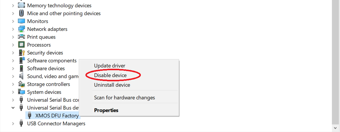
Fig. 16 Disable the control device in Device Control#
Click Yes if the message below appears:
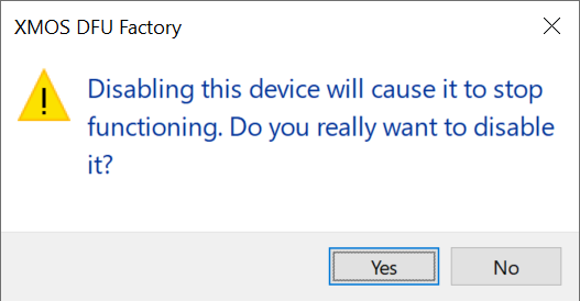
Fig. 17 Accept warning message#
Note
The driver can be re-enabled again by selecting Enable device after a right-click on the device in Device Manager
Download the third-party installation tool Zadig from https://zadig.akeo.ie/.
Open Zadig and select XMOS Control (Interface 3) from the list of devices. If the device is not present, ensure Options -> List All Devices is checked.
Select libusb-win32 from the list of drivers.
Click the Install Driver button and wait for the installation to complete.
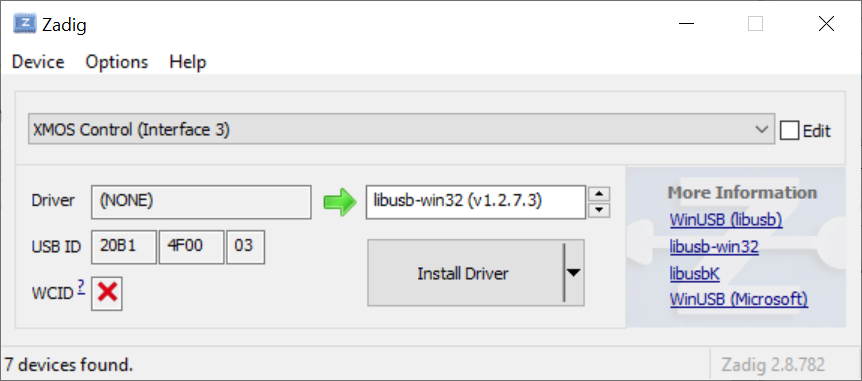
Fig. 18 Selecting the libusb-win32 driver in Zadig for the Control Interface#
Connecting to the XVF3800 Device#
To use the host application, login to the host machine, either directly,
via a VNC connection or ssh and to open a terminal command line.
Change to the directory containing xvf_host(.exe). If the host tools have been added to the path as
above this step is not needed.
The xvf_host(.exe) device control application is run from the command line.
To check connection to the XVF3800, any command can be given; for example, the command
xvf_host(.exe) --use <protocol> VERSION
where <protocol> can be i2c, spi or usb depending on the interface used in the
specific firmware. The default control protocol is USB.
This command should return “2 0 0”.
xvf_host Command Syntax#
The general syntax of the xvf_host(.exe) command is
xvf_host(.exe) [ command | option ]
               [ -u <protocol>] [ -cmp <path> ] [ -br ] [ command | option ]
More documentation on the available options in the use of the host application are found with
xvf_host(.exe) --help
A full list of control commands may be found using:
xvf_host(.exe) --list-commands
These commands are also listed in an Appendix of this User Guide.
It is possible to read all the control parameter settings from the XVF3800 using the following option:
xvf_host(.exe) --dump-params
To support scripted set up of the XVF3800 it is possible to save the list of commands in a text file (.txt) which can be executed using:
xvf_host(.exe) --execute-command-list <command_file>.txt
Further options for saving and loading parameter sets
can found by using the --help option or in the section of the
User Guide on tuning the device where their usage is described.
Microphone orientation#
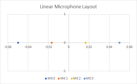
The XVF3800 supports arbitrary microphone geometries which can be specified in configuration files. Two default configurations are included in the release package that are aligned to the geometries supported on the XK-VOICE-SQ66 development kit.
The linear configuration (-lin) comprises 4 microphones in a linear array, spaced 33mm apart, as shown below:
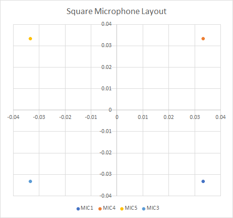
The square configuration (-sqr) uses a 4 microphone array with a 66mm distance along each side as shown below.
Note
These configurations are selected by a multiplexer on the XK-VOICE-SQ66 development kit when the device boots. They have to be configured as part of the firmware build and cannot be changed in operation.
The microphone numbers in the diagrams above correspond to the labels on the XK-VOICE-SQ66 development kit board.
In the firmware configuration these microphones are mapped to 4 microphone indexes: MIC[0..3] which are used
in the firmware and when using xvf_host. The mapping of the logical indexes and the physical microphones on the XK-VOICE-SQ66 development kit is shown in the table below:
Logical |
Physical Microphone |
|
|---|---|---|
Microphone Index |
Linear Config |
Square Config |
MIC0 |
MIC0 |
MIC1 |
MIC1 |
MIC1 |
MIC4 |
MIC2 |
MIC2 |
MIC5 |
MIC3 |
MIC3 |
MIC3 |
Beam forming subsystem and Direction of Arrival indicator#
As described in XVF3800 datasheet, the system uses a set of beams to focus on speakers and reduce unwanted sounds and reverberation in the output signal. The XVF3800 uses a free running beam that scans the environment, identifies likely speakers and switches one of the two focused beams to that direction.
In normal operation the audio pipeline automatically selects the best signal to output.
It is possible to read back the direction that the beams are currently pointing.
This is done with the xvf_host command AEC_AZIMUTH_VALUES. The output of the command contains 4 values:
Focused beam 1
Focused beam 2
Free running beam
Auto selected beam
Each value is the azimuth angle of the corresponding beam, provided in both radians and degrees. The coordinate system used depends on the hardware configuration. The diagrams below show the azimuth angles relative to the XK-VOICE-SQ66 development kit in the two default configurations.
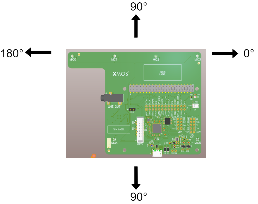
Fig. 19 Azimuth angle in linear configuration (note - 0 to 180 degrees only)#
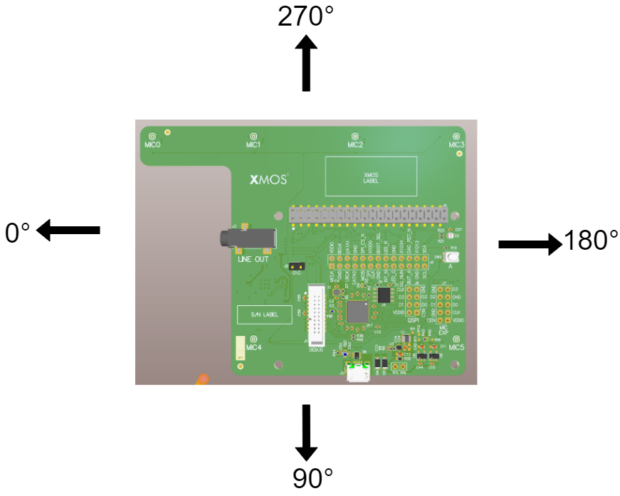
Fig. 20 Azimuth angle in square configuration#
Using azimuth data For Direction of Arrival indication#
The auto selection algorithm will switch between beams rapidly in some circumstances. The two focused beams update relatively slowly, but the free running beam is designed to be sensitive so that it can rapidly pick up the speech signal for a new talker entering the soundscape. As a result it can also pick up any noise signals present.
To provide maximum flexibility to system designers, the XVF3800 only provides raw azimuth data. In most use cases this data will require post processing - e.g. to only track the slow focused beams or to add a voice activity detector to indicate when the direction of arrival data is valid.
Example Uses#
The xvf_host tool allows the configuration of the XK-VOICE-SQ66 development kit to be changed during operations. The following examples illustrate some common operations.
Note
All examples below will target UNIX-based platforms
Output Selection#
By default, the left (first) channel of the device’s output is the processed output from the XVF3800’s AEC and beamforming stage, while the right (second) channel is the raw input from one of the microphones after amplification. This selection provides a good comparison between the raw and processed audio. The selected outputs may be changed by using the AUDIO_MGR_OP_L and AUDIO_MGR_OP_R commands. These commands each take two integers defining the mux routing settings, described as a pair of (category, source) values.
The available categories and sources are as detailed in Table 26.
Category |
Sources |
|---|---|
0: Silence |
0: Silence |
1: Raw microphone data - before amplification |
0,1,2,3: Specific microphones accessed by index, no system delay applied |
2: Unpacked microphone data |
0,1,2,3: Unpacked microphone signals. If using packed input, access packed microphone data though this category. This data is undefined when not using packed input. |
3: Amplified microphone data with system delay |
0,1,2,3: Specific microphones accessed by index. This category provides the microphone signal passed to the SHF logical cores for processing. Source 2 is the default setting for the right channel output. |
4: Far end (reference) data |
0: Far end data received over I2S, post sample rate conversion to 16 kHz if required |
5: Far end (reference) data with system delay |
0: Far end data received over I2S, post sample rate conversion to 16 kHz if required, and with system delay applied |
6: Processed data |
0,1: Slow-moving post-processed beamformed outputs, 2: Fast-moving post-processed beamformed output, 3: The “auto-select” beam; chooses the best of the previous three beams as an output, recommended option for selecting the beamformed outputs |
7: AEC residual data |
0,1,2,3: AEC residuals for the specified beam |
8: User chosen channels |
0,1: These currently copy the auto-select beam (category 6, source 3) and are the default setting for the left channel output. |
9: Post SHF DSP channels |
0,1,2,3: All output channels from user post SHF DSP |
10: Far end at native rate |
0,1,2,3,4,5: Data passed from I2S logical core to Audio Manager logical core. All sources carry useful data if the external interface rate is 48 kHz. Only sources 0 and 1 carry useful data if the external interface rate is 16 kHz. See the Data Plane Detailed Design section in the Programming Guide for information on the interface between these two logical cores. |
11: Amplified microphone data before system delay |
0,1,2,3: Specific microphones accessed by index. |
12: Amplified far end (reference) with system delay |
0: Far end data received over I2S, post sample rate conversion to 16 kHz if required, and with a configurable fixed gain and system delay applied. This category provides the reference signal passed to the SHF logical cores for processing. |
Fig. 21 shows the available categories and sources. Inputs to the category multiplexer that have no preliminary multiplexer only support a single source.
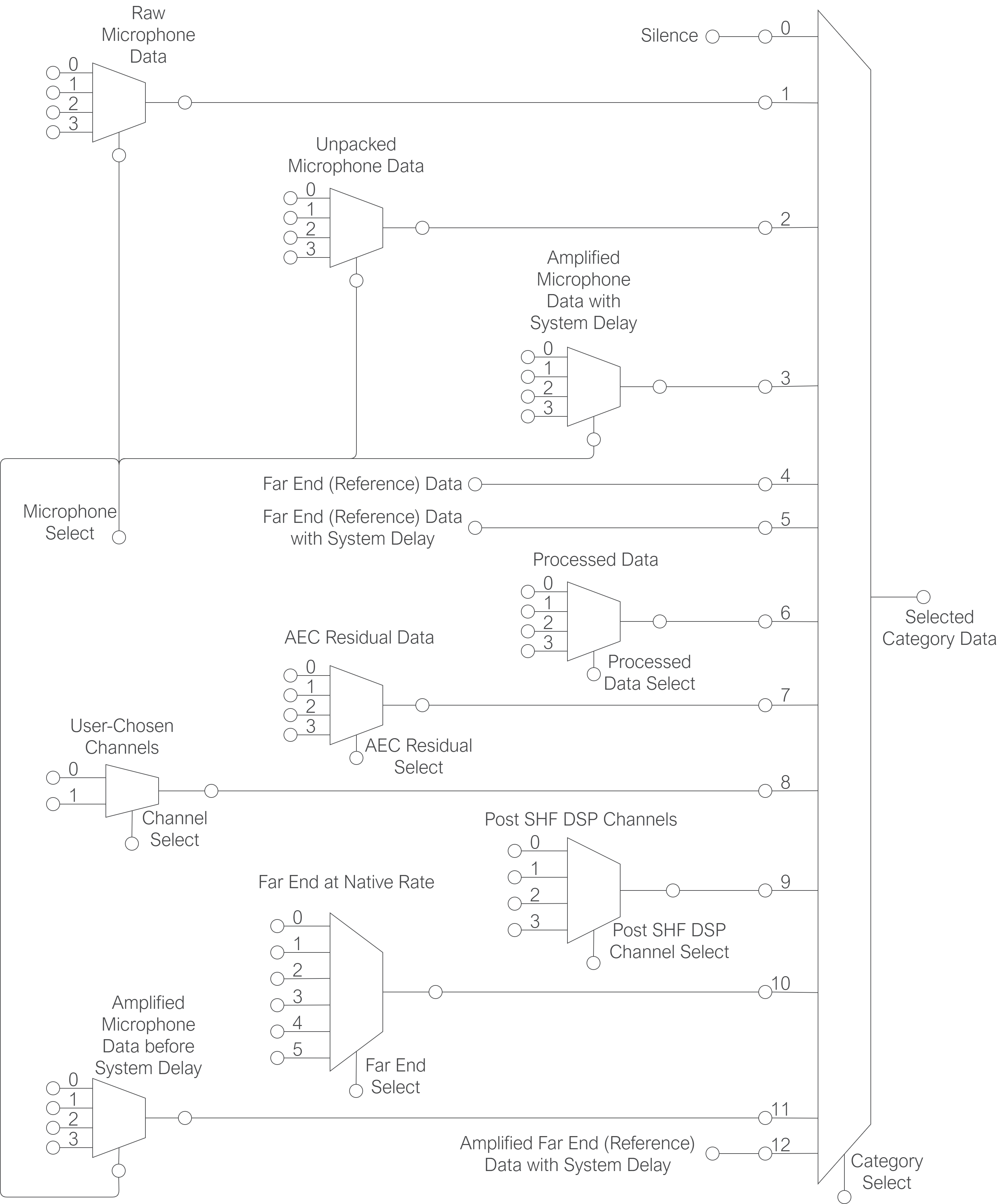
Fig. 21 Output Selection Multiplexers#
For example, to set the left output to the 4th raw microphone signal (without gain applied), issue the command
xvf_host AUDIO_MGR_OP_L 1 3
This will set the left channel to output the 4th (0-indexed) microphone signal of the 4 present. To reset this channel back to its default value, issue
xvf_host AUDIO_MGR_OP_L 8 0
to set the channel to the postprocessed auto-selected output beam.
Similarly, the right channel may be set to any desired category/source; to reset to its default value, issue
xvf_host AUDIO_MGR_OP_R 3 2
Setting an Output Pin#
The xvf_host can be used to configure the General Purpose Outputs on the XVF3800.
To turn on the LED on the XK-VOICE-SQ66 development kit issue the following commands
xvf_host gpo_port_pin_index 0 6
xvf_host gpo_pin_pwm_duty 100
and to turn it off use
xvf_host gpo_pin_pwm_duty 0
Note
The gpo_port_pin_index selects a port and subsequent gpo_pin_xxx commands only act on that pin.