Some Acoustic Design Guidelines#
This chapter presents a brief guide to a number of introductory acoustic considerations that designers should take into account when integrating the XVF3800 into their end product.
It should be stressed that a more ideal acoustic design will result in fewer compromises needing to be made whilst configuring the XVF3800. Designers should invest time in the acoustic design of the end product in order to optimise the overall product performance.
Microphones#
The XVF3800 requires 4 microphone inputs. These microphones may be omnidirectional; no additional benefit has been observed from the use of e.g. cardioid polar patterns.
Microphones chosen for a design should exhibit a signal-to-noise ratio (SNR) greater than 67 dB. This ensures a sufficiently low microphone self-noise, allowing a low enough noise floor for the XVF3800 to function effectively. Matched microphones are however not necessary. Total Harmonic Distortion (THD) should be less than 1%, although with modern MEMS microphones this is usually the case so long as the microphone is not operating near its acoustic overload point.
For compatibility with the XVF3800, microphones chosen should be digital MEMS microphones with a PDM output. These will be clocked at 3.072 MHz, with a decimation factor applied in firmware to generate the sampling rate used internally.
With loudspeakers operating at their loudest volume, microphones should not reach acoustic overload. At loudest loudspeaker volume, a headroom of 6 to 10 dB is a reasonable goal. It is important that the microphones are not driven into a non-linear response due to the volume of the loudspeakers in the end product.
The XVF3800 supports both circular and linear microphone arrays. However, regardless of the geometry chosen, at least 2 (and preferably more) of the microphones should be at least 10 cm apart. This is in order to ensure sufficient low frequency coupling between microphones, allowing more coherent and natural speech to be captured.
With zero input (i.e. a silent room), there should be low coherence between microphone signals - that is to say, the self-noise of the microphones chosen should not be correlated between microphones. If correlation is observed with zero input, this usually indicates that there exists some common-mode interference between the microphone signals. The presence of correlated noise has a negative effect on the performance of the XVF3800, and so this should be as minimal as possible. To estimate coherence between pairs of microphones at frequencies up to the Nyquist limit (which in this system will be 8 kHz), the provided coherence.py script can be used to generate a plot similar to that shown in Fig. 22, where the blue line shown is real data from two microphones in a silent room and the red line is a theoretical coherence plot between two perfect microphones measuring diffuse noise. This theoretical model is a sinc2` function with its maximum at DC and its first zero crossing at f given by f = c / 2d, where c is the speed of sound (in m/s) and d is the distance between microphones (in m). The coherence.py script may be used as:
python3 coherence.py <mic0_1.wav>
The signal mic0_1.wav should be a 2 channel, 16 kHz WAV file with two microphone signals, which should be captured in silence; to capture these signals using the XVF3800’s output, issue:
xvf_host AUDIO_MGR_OP_L 1 0
xvf_host AUDIO_MGR_OP_R 1 1
Record 30 seconds of output from the device, and repeat for the other microphones:
xvf_host AUDIO_MGR_OP_L 1 2
xvf_host AUDIO_MGR_OP_R 1 3
Further information on the use of the host application to capture output can be found in [FINAL: link to the hardware setup guide section where we talk about this] and documentation of this script may be found in its docstring.
For optimal algorithmic performance, the coherence between each possible pair of microphones should be less than 0.1. All possible pairs of microphones should be tested; this will result in a total of 6 plots.
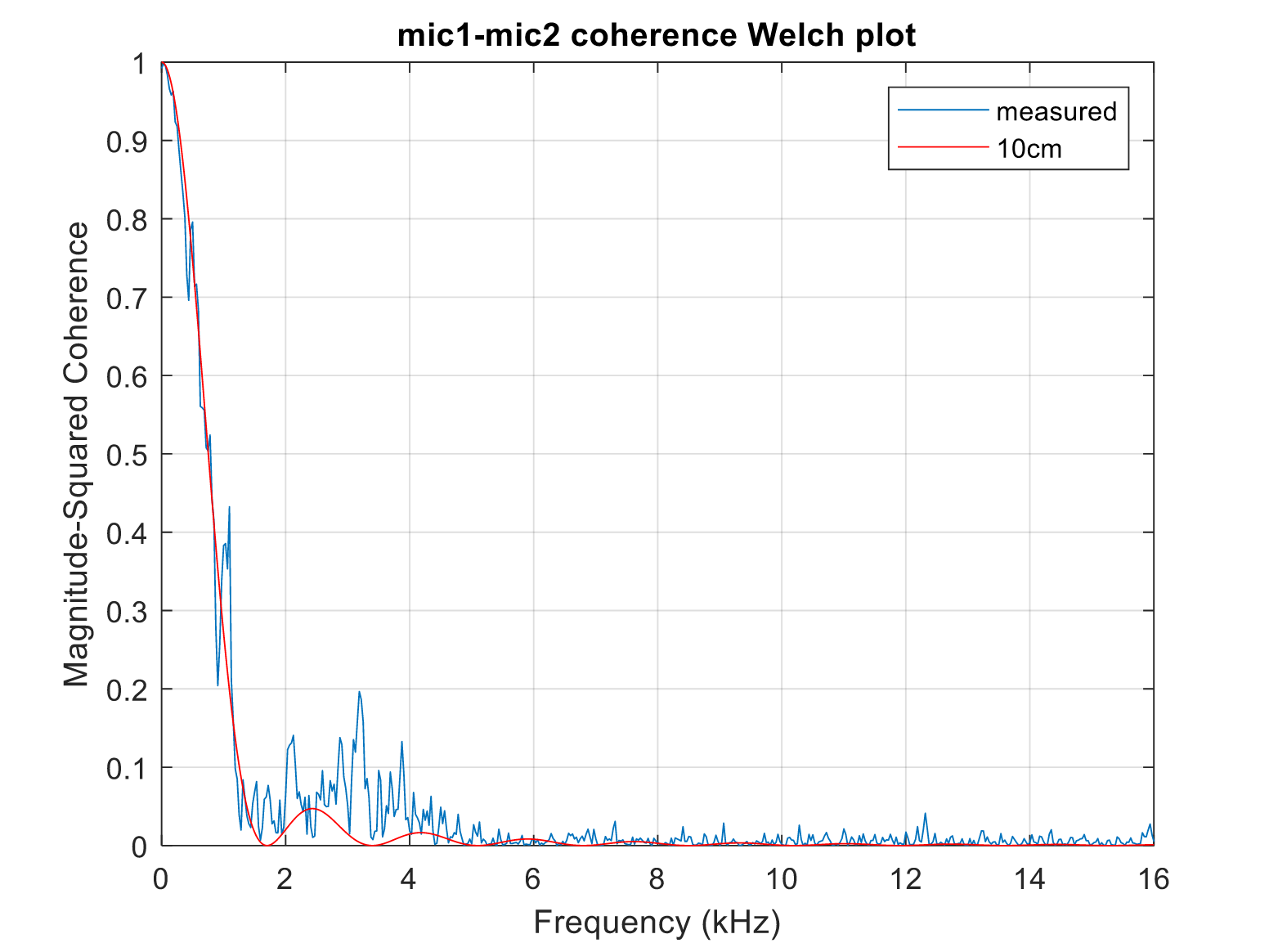
Fig. 22 Sample coherence plot between two microphones, where the blue line is real data and the red line is a theoretical coherence between two perfect microphones recording diffuse noise#
Loudspeaker(s)#
The most pressing consideration when incorporating loudspeakers into a design using the XVF3800 is the minimisation of non-linearities within the design. Whilst the XVF3800 features a linear echo canceller (the AEC), and whilst it can also suppress tail echo and non-linear echo, it is advisable to keep any non-linearities in the design to a minimum in order to guarantee optimal intelligibility and algorithmic performance.
The two main sources of non-linearity in a design arise from mechanical coupling between a loudspeaker and the microphones and from non-linearities present in the loudspeaker/amplifier stage itself. Efforts should be made to ensure that any loudspeakers are appropriately isolated from the microphones and placed physically as far away as feasible. Isolation may take the form of mechanical decoupling from the rest of the enclosure and/or the use of soundproofing material between loudspeakers and the microphones. Additionally, product enclosures should be designed in such a manner as not to introduce non-linear effects; they should not rattle, click, vibrate, or otherwise introduce extraneous noise during normal operation.
Non-linearities present in the loudspeaker/amplifier stage are more difficult to provide generalised advice on.
Loudspeakers and amplifiers should be specified such that at nominal operating volume they are both operating within their linear region; this usually pushes design decisions towards larger or more powerful loudspeakers. As noted in the previous section, the loudspeakers at their maximum level should not be so loud that they push the microphones in the design to acoustic overload.
A THD of below 3 to 5%, measured over the full frequency range at the maximum level, is desirable. Designers should note that the THD for loudspeakers is typically only specified in datasheets at 1 kHz. THD can also be introduced by the amplifier used; it is important that amplifiers are chosen such that the overall THD of the loudspeaker system is minimised wherever possible.
Finally, it is important to consider the effect of loudspeaker placement on the far-field sensitivity of the device’s microphones. In general for a given nominal level, the closer a microphone is placed to a loudspeaker the lower its gain must be in order to avoid clipping. This means that the closer a loudspeaker is located to a microphone, the lower the overall system gain will be, and therefore the lower the far-field sensitivity of the device.