Modifying the Software#
Adding a Control Command#
The XVF3800 software allows for easily extensible control. Each time the firmware is built, the command definition YAML files are parsed and the firmware hooks and enums are updated automatically. See Building the Software for how to build the XVF3800 firmware.
The command definition files can be found in applications/app_xvf3800/cmd_map_gen/yaml_files. There is a file for each control servicer within the firmware. The control servicers are:
application_cmds.yaml- This is where build information is accessed and some test features. The application servicer does not directly connect to any peripherals, however commands requiring internal storage or calling a user API may be added here.audio_cmds.yaml- This is where high-level aspects of the audio framework including SRC, packing, I2S and user-DSP are accessed. If extending the DSP capabilities of the design it is likely that commands may be added here, for example to control user-DSP. See Adding Custom Digital Signal Processing. Note that two tasks are controlled by this servicer (Audio Manager and I2S) with the I2S task being accessed via a shared-memory structure.io_config_cmds.yaml- This is where GPIO parameters are accessed. Commands are already provided for manipulating many aspects of these pins, although any custom requirements involving GPIO access may be added here.aec_cmds.yaml- This is where high level voice-DSP parameters are accessed as well as AEC information. The voice-DSP is not modifiable other than the published API. It is not expected that this file will need to be modified.pp_cmds.yaml- This is where high level voice-DSP parameters are accessed as well as post processing information. The voice-DSP is not modifiable other than the published API. It is not expected that this file will need to be modified.
Adding a new control command#
This process is illustrated by adding a simple read/write parameter via application_cmds.yaml. As an example of how to extend this to controlling IO, see the FAR_END_DSP_ENABLE parameter contained in audio_cmds.yaml.
First, add a command to the YAML file. The valid types that can be used for command parameters are as follows:
TYPE_INT32
TYPE_UINT32
TYPE_INT16
TYPE_UINT16
TYPE_INT8
TYPE_UINT8
TYPE_CHAR
TYPE_FLOAT
TYPE_RADIANS
Any number of these parameters may be defined in a control command, up to the total maximum command size of 64 bytes. Commands attributable to the pp_cmds servicer are exceptions; these are limited to 20 bytes.
The following access permissions may be assigned to parameters:
CMD_READ_ONLY
CMD_WRITE_ONLY
CMD_READ_WRITE
For write commands, a range must be provided for each value. If no value range is specified for such commands, the firmware code will fail to compile. The ranges must be listed in the value_ranges array and must follow one of the two formats:
list of intervals - each interval is listed using the syntax [A .. B]
the syntax is the same for both integers and float values
multiple intervals can be specified, for example [0 .. 5, 10 .. 15]
all the intervals must be closed, meaning that they include all the limit points
if only one value is valid, the range can be specified as [E .. E]
any value is valid - this is declared using the word any and the range depends on the maximum and minimum values of the specific type. For example, TYPE_UINT8 can have values from 0 to 255.
An example of a command with two arguments, where the first requires a list of intervals and the second accepts any value, is shown below:
value_ranges:
    - value0: [0 .. 5, 10 .. 15]
    - value1: any
Note
The host control application performs range checking before sending the control command to the device and it returns an error if any argument value is out of range.
An example of adding a command to application_cmds.yaml is shown below. The position in the list at which the command is added is not important so long as it is in the appropriate section.:
- cmd: MY_INTERNAL_REGISTER
  number_of_values: 1
  type: CMD_READ_WRITE
  help: A simple example of setting / getting a variable in the firmware
  value_type: TYPE_UINT32
Next, in the appropriate servicer C file, add the handlers for the command. In this case we are adding the following code to applications/app_xvf3800/src/control_plane/application_servicer.c:
// Global variable to get or set
uint32_t my_var = 0;
In the function control_ret_t application_servicer_read_cmd() add the following case. Note the pre-pending of the resource ID to the command name:
case APPLICATION_SERVICER_RESID_MY_INTERNAL_REGISTER:
    memcpy(payload, &my_var, sizeof(my_var));
    break;
In the function control_ret_t application_servicer_write_cmd() add the following case:
case APPLICATION_SERVICER_RESID_MY_INTERNAL_REGISTER:
    memcpy(&my_var, payload, sizeof(my_var));
    break;
Next, build the firmware and host app; see Building the Software for instructions on this. Test the new command:
./xvf_host MY_INTERNAL_REGISTER
0
./xvf_host MY_INTERNAL_REGISTER 1066
./xvf_host MY_INTERNAL_REGISTER
1066
Adding Custom Digital Signal Processing#
The XVF3800 supports the addition of user DSP at two parts of the signal path. These points are:
Far-end DSP between the far-end (reference) input and the start of the far-field voice pipeline. This allows the far-end signal to be processed to allow for speaker/amplifier imperfections and a copy of the pre-processed far-end be sent to the voice pipeline (and optionally over I2S to the DAC) to ensure optimum AEC performance.
Voice post-processing. While the voice processing offers a wide range of typically needed functions such as AGC, high-pass filtering and automatic beam selection, some users may wish to augment these functions.
Fig. 39 shows the audio paths for the far-end DSP as well as where up/down-sampling may occur. Voice post-processing occurs immediately after the voice pipeline and before the processed microphone signals are sent to the host.
Note
USB functionality is not currently supported in the XVF3800.
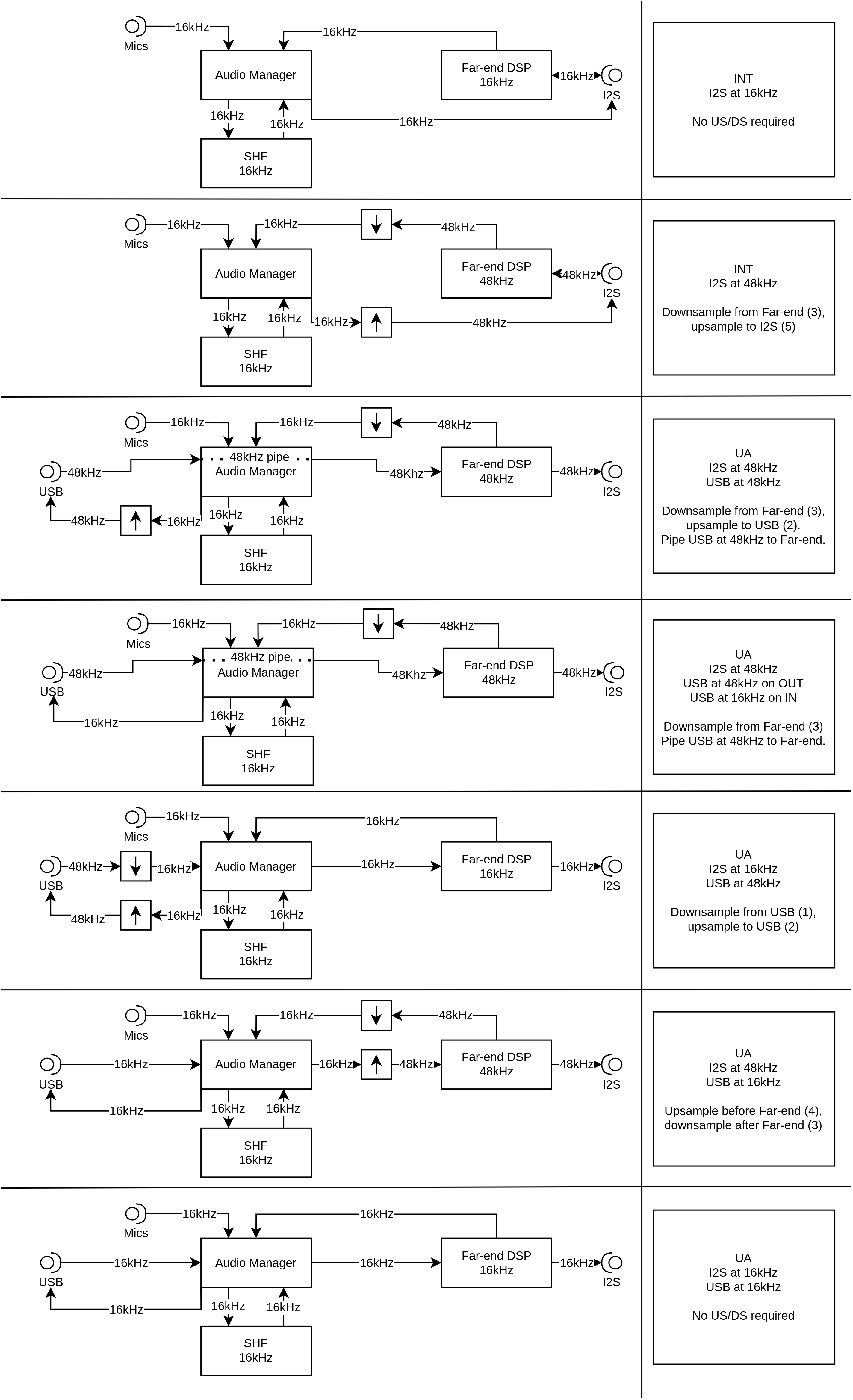
Fig. 39 Audio paths for far-end DSP and where up/down-sampling may occur in the XVF3800.#
Both DSP hooks provide a sample-based processing API. This means a single sample is processed at each time. The reason for this is to reduce latency (block based algorithms introduce a minimum latency of the block size) and to simplify the integration into the main firmware framework. Various DSP functions are available in lib_xcore_math including FIR filters and Biquad IIR filters. An example of the latter is given further on.
Note
Integration of user DSP consumes processing cycles from the processor. These are limited according to the build and host sample rates used. Please see Meeting timing for details.
The API for the user-DSP functions is transcluded below from applications/app_xvf3800/src/user_dsp/user_dsp.h:
// Copyright 2022-2023 XMOS LIMITED.
// This Software is subject to the terms of the XCORE VocalFusion Licence.

#ifndef __USER_DSP_H_
#define __USER_DSP_H_

#include "aec_cmds.h"
#include "shf_wrapper.h"
#include <stddef.h>

/// There is a timing limit on the time spent in these functions. Please use the
/// minimum idle time control commands in conjucntion with the TEST_CORE_BURN command to
/// characterise the amount of cycles available.
/// The far_end_dsp function is called from I2S and so check min_idle time for that task
/// The far_end_dsp function is called from Audio and so check min_idle time for that task


/// @brief callback to pre-process one sample of far end before outputting to DAC/SHF DSP input
/// Note that this callback runs at the I2S rate (16 or 48 kHz).
/// @param far_end_sample      input and output (sample is processed in place)
/// @param far_end_dsp_enable  Set to 1 to enable, 0 to disable. This is handled by the user.
void far_end_dsp(int32_t far_end_samples[BECLEAR_NUMBER_OF_FAR], bool far_end_dsp_enable);

/// @brief callback to post-process one sample of audio after the SHF voice DSP stage
/// Note that this callback runs at the SHF sample rate 16kHz.
/// @param out processed output buffer
/// @param post_shf_processed_mic_samples input
/// @param azimuth direction of arrival data on the 3 tracking beams (not auto select), Note
/// that this only gets updated every 256 samples.
/// @param aec_residuals output of the BeClear AEC stage
void post_shf_dsp(int32_t out[BECLEAR_NUMBER_OF_OUTPUTS],
                  int32_t post_shf_processed_mic_samples[BECLEAR_NUMBER_OF_OUTPUTS],
                  int32_t aec_residuals[BECLEAR_NUMBER_OF_MICS],
                  float azimuths[AEC_RESID_AEC_AZIMUTH_VALUES_NUM_VALUES]);

#define USER_DSP_NUM_OUTPUT_CHANNELS 2

/// @brief called immediately after post_shf_dsp and will be used to determine the
/// channels that MUX_USER_CHOSEN_CHANNELS will consist of. It also sets the azimuth
/// of each chosen channel so that it can be requested via control command.
///
/// @param[in,out] out_idx 2 chosen channels from `out` which were written by
///    the function `post_shf_dsp`. Before being passed to beam_selection,
///    out_idx will be populated by the suggested indices.
/// @param[out] out_azimuths azimuths of the two channels that have been
///    selected. Most likely a copy of the correct input from above.
void beam_selection(uint8_t out_idx[USER_DSP_NUM_OUTPUT_CHANNELS],
                    float out_azimuths[USER_DSP_NUM_OUTPUT_CHANNELS]);

#endif
Meeting Timing#
When adding DSP, it is important to check timing. It is not sufficient just to check audio is playing cleanly because the available cycles within the XVF3800 varies significantly depending on operation and will increase under certain conditions. A comprehensive method for checking worst case timing is included and can be found in the testing the software section of the Programming Guide.
Adding control to user DSP#
In some cases it may be desirable to add a custom control command to allow the host application to enable/disable or adjust the user DSP. The steps in Adding a Control Command show how to add controls to the firmware and the below examples include adding a control for each case.
The Far-end reference DSP already has a built-in control which is AUDIO_MGR_FAR_END_DSP_ENABLE. It is possible to add further controls if needed.
Far-end Reference#
The far-end DSP offers the opportunity to add processing between the host audio signal and the DAC output. This is particularly important if adding non-linear processing (eg. bass-enhancement, dynamic-range compression) which will cause a degradation in AEC performance if the far-end reference to the voice pipeline differs from what is being played through the speaker.
The rate of the DSP is the host interface rate. For example, if I2S runs at 48 kHz, then the far-end DSP also runs at 48 kHz. The samples will not be sent to the voice pipeline until after the far-end DSP has occurred and will be down-sampled if required.
Because the far-end DSP block will add delay to the voice pipeline reference signal, it is essential that any delay added is not so large that the direct path (speaker to mic) of the far-end signal arriving at the microphones gets to the voice pipeline before the far-end processed signal does. This non-causal relationship will cause a rapid degradation in AEC performance. For more information on this, including how to measure this effect, see the Tuning the Software section of the User Guide.
Depending on the external audio path and the type of processing applied (linear vs non-linear) it may be necessary to add an additional audio line. For example, an I2S connected system may need one audio line for the reference input, one audio line for the processed microphone output and an additional line for the processed far-end output to the DAC. Where the far-end audio source is USB, this is not necessary since the far-end processed output will always be sent to the DAC pin as well as the voice pipeline input.
The XVF3800 allows provision of a third I2S line for far-end processed output using the following steps:
Increase
appconfNUM_I2S_PINS_OUTinapp_conf.hfrom 1 to 2. This will enable PORT_I2S_DATA2 as an I2S output pin. The default is to set the second pin to output the post-processed far-end input with sample rate conversion disabled.Set
USE_FAR_END_DSPinfar_end_dsp.cto 1. Far-end DSP is kept out of the standard build to avoid using extra memory and processing cycles, and to avoid modifying the far-end when not needed.Make sure the DAC input is connected to the far-end DSP processed signal. If using USB, it is possible that the hardware will not easily support routing the second I2S line to the DAC. Therefore, in the USB build, the pin formerly used as the I2S input to the device may be repurposed as an I2S output. To take advantage of this, keep
appconfNUM_I2S_PINS_OUTset to 1 and instead use the audio MUX command to route the post-processed far-end signal to the output. The following commands ensure up-sampling is disabled and route far-end DSP signal to the output:./xvf_host AUDIO_MGR_OP_UPSAMPLE 0 0 ./xvf_host AUDIO_MGR_OP_ALL 10 0 10 2 10 4 10 1 10 3 10 5
A control command has already been provided which passes a boolean to the far_end_dsp() function, which allows the user to enable and disable the far-end DSP and verify its functionality. This may be controlled using:
./xvf_host AUDIO_MGR_FAR_END_DSP_ENABLE 1
./xvf_host AUDIO_MGR_FAR_END_DSP_ENABLE 0
For example purposes, a three stage biquad filter has been implemented which boosts bass and treble by 6 dB and cuts mid-range by 6 dB. This will produce a noticeable effect suitable for demonstration purposes and to verify that the DSP is active. This example has coefficients that have generated assuming a 48 kHz sample rate. They will not work properly at 16 kHz and will need to be re-calculated.
The code is shown below, transcluded from applications/app_xvf3800/src/user_dsp/far_end_dsp.c:
// Copyright 2022-2023 XMOS LIMITED.
// This Software is subject to the terms of the XCORE VocalFusion Licence.

#include "user_dsp.h"

#ifndef USE_FAR_END_DSP
    #define USE_FAR_END_DSP 0
#endif

#if USE_FAR_END_DSP
#include "xmath/xmath.h"

// Simple example DSP that processes far end using an EQ. Note the coeffs are correct for 48kHz only
// Each filter_biquad_s32_t can store (up to) 8 biquad filter sections
#define SECTION_COUNT   3

filter_biquad_s32_t filter[BECLEAR_NUMBER_OF_FAR] = {{
    // Number of biquad sections in this filter block
    .biquad_count = SECTION_COUNT,

    // Filter state, initialized to 0
    .state = {{0}},

    // Filter coefficients
    // Section 0: Frequency = 100 Hz, Q Factor = +1.2,  Gain = +6.0dB
    // Section 1: Frequency = 1000 Hz, Q Factor = +0.2, Gain = -6.0dB
    // Section 2: Frequency = 8000 Hz, Q Factor = +1.3, Gain = +6.0dB
    .coef = {
        { Q30(+1.00286226693868),  Q30(+0.86561763867029),  Q30(+1.58124059575259)},
        { Q30(-1.98608850422494),  Q30(-1.44869047773446),  Q30(-1.32398889950623)},
        { Q30(+0.98346660965693),  Q30(+0.59557353208939),  Q30(+0.56062804987035)},
        { Q30(+1.98614845462853),  Q30(+1.44869047773446),  Q30(+0.45958190453639)},
        { Q30(-0.98626892619203),  Q30(-0.46119117075968),  Q30(-0.27746165065311)}
        }
}};


void far_end_dsp(int32_t far_end_samples[BECLEAR_NUMBER_OF_FAR], bool far_end_dsp_enable)
{
    // See note in user_dsp.h and user documentation about timing constraints
    if(far_end_dsp_enable)
    {
        for(int channel = 0; channel < BECLEAR_NUMBER_OF_FAR; channel++)
        {
            far_end_samples[channel] >>= 1; // Simple 6db pre-attenuate to account for gain in filter
            far_end_samples[channel] = filter_biquad_s32(&filter[channel], far_end_samples[channel]);
        }
    } else {
        for(int channel = 0; channel < BECLEAR_NUMBER_OF_FAR; channel++)
        {
            far_end_samples[channel] >>= 1; // Simple 6db attenuate to account for filter gains to give similar apparent volume
        }
    }
}

#else

void far_end_dsp(int32_t far_end_samples[BECLEAR_NUMBER_OF_FAR], bool far_end_dsp_enable)
{
    // Do nothing - samples unmodified
}

#endif
Testing the effect on available cycles, we can see a modest drop from the three stage biquad of just 85 x 10 ns = 0.85 us; this is due in part to the use of the Vector Processing Unit (VPU), which is highly efficient for signal processing purposes. Note that the idle time is not calculated until I2S runs:
./xvf_host TEST_CORE_BURN 1
./xvf_host I2S_MIN_IDLE_TIME
2083
aplay <short wav>
aplay <short wav>
aplay <short wav>
./xvf_host I2S_MIN_IDLE_TIME
1245
./xvf_host AUDIO_MGR_FAR_END_DSP_ENABLE 1
aplay <short wav>
aplay <short wav>
aplay <short wav>
./xvf_host I2S_MIN_IDLE_TIME
1160
Voice post-processing#
As the name suggests, this DSP hook allows the user to add any required DSP after the microphone signals have passed through the voice pipeline. The rate of the processing is always the rate of the voice pipeline (nominally 16 kHz). A number of audio signals are available including multiple output beams and AEC residuals which are the echo-cancelled only signals for each of the four microphones.
To allow more informed selection of the output beam, the Direction Of Arrival (DOA) azimuths are also provided to allow custom logic to choose the desired signal.
Adding processing to this part of the chain will not affect the performance of the core voice pipeline; however, it will add to the total delay through the device from microphones to output interface.
Follow the same steps as per the Far-end Reference except when checking timing, please use AUDIO_MGR_MIN_IDLE_TIME instead of I2S_MIN_IDLE_TIME since the processing cycles are consumed from a different task. The Testing the Software section also provides detailed information on how to check timing.
Modifying Existing Functionality#
The XVF3800 provides the ability to customise the initialisation code for any connected hardware at firmware boot time. During run-time, the GPIO pins may be modified via control commands from the host control application. Initialisation typically involves setting GPO pins to control board level features such as LEDs and configuring I2C connected devices such as an IO expander, a DAC, or a digital amplifier. The code for user hardware initialisation can be found in applications/app_xvf3800/src/user_config. The main file to be modified is user_config.c which is shown below.
// Copyright 2022-2023 XMOS LIMITED.
// This Software is subject to the terms of the XCORE VocalFusion Licence.

#include "FreeRTOS.h"
#include "app_conf.h"
#include "user_config.h"
#include "io_config_servicer.h"
#include "dac3101.h"

// This file contains the user hardware configuration code. It uses the implementations in dac3101.h (EVK3800)
// and the lower level hardware implementations in dac_port.c

int user_init_hardware(device_control_t *device_control_gpio_ctx)
{
    int errors_encountered = 0;

    rtos_printf("user_init_hardware\n");

#if !defined(MIC_ARRAY_TYPE)
#error
#endif
#if MIC_ARRAY_TYPE == BECLEAR_LINEAR_ARRAY
    write_gpo_pin(device_control_gpio_ctx, GPO_SQ_nLIN_PIN, 0);
#elif MIC_ARRAY_TYPE == BECLEAR_CIRCULAR_ARRAY
    write_gpo_pin(device_control_gpio_ctx, GPO_SQ_nLIN_PIN, 1);
#else
    #error MIC_ARRAY_TYPE invalid
#endif

    // De-assert HOST INTERRUPT line
    write_gpo_pin(device_control_gpio_ctx, GPO_INT_N_PIN, 1); // No interrupt to host asserted when high

#if (appconfUSER_CONFIG_ENABLED == 1)
    // Reset the DAC
    dac3101_codec_reset(device_control_gpio_ctx);

    errors_encountered |= dac3101_init(appconfLRCLK_NOMINAL_HZ);
#endif

    // Test that we can turn on a LED by sending a command from this task to the GPO task
    // Note even though LEDs are active low, we have setup the LED pins in gpo_servicer to drive negaive logic
    for(int i = 0; i < 5; i++){
        write_gpo_pin(device_control_gpio_ctx, GPO_LED_GREEN_PIN, 1); // Turn the green LED on
        vTaskDelay(pdMS_TO_TICKS(100));
        write_gpo_pin(device_control_gpio_ctx, GPO_LED_GREEN_PIN, 0); // Turn the green LED off
        vTaskDelay(pdMS_TO_TICKS(100));
    }

    return errors_encountered;
}
This file is currently configured for the XK-VOICE-SQ66 evaluation kit and its associated hardware set.
In this file we can see the following actions taken:
Setting of GPO output line on the XK-VOICE-SQ66 evaluation kit to control mic array topology.
Setting of GPO output line to de-assert the host interrupt line.
Resetting of the DAC. See the next section Digital to Analogue Converter Configuration for details.
Configuring the DAC. See the next section Digital to Analogue Converter Configuration for details.
Flashing the green LED five times to show that booting of the XVF3800 is occurring.
Note
The control plane part of the XVF3800 firmware, responsible for servicing control commands from the host, will not start until the call to user_init_hardware() is complete. Any control commands issued by the host before initialisation is complete will not be serviced.
Digital to Analogue Converter Configuration#
Each DAC or digital amplifier selected will normally have its own set of registers that need to be configured. There are two parts to the DAC configuration code. The first is the abstraction layer responsible for providing the I2C, GPO, and wait functions. These may need to be modified if the GPO responsible for resetting the DAC or the I2C register access methods needs to be altered. This file can be seen below, transcluded from applications/app_xvf3800/src/user_config/dac_port.c:
// Copyright 2022-2023 XMOS LIMITED.
// This Software is subject to the terms of the XCORE VocalFusion Licence.

// This file contains the implementations of the DAC configuration steps such as which registers to write with which values
// Note there are currently two implementations because in I2C slave we init the DAC pre-RTOS

/* FreeRTOS headers */
#include "FreeRTOS.h"

/* App headers */
#include "xcore/port.h"
#include "rtos_i2c_master.h" // Includes "i2c.h" too
#include "platform/driver_instances.h"
#include "io_config_servicer.h"
#include "user_config.h"
#include "dac3101.h"


void dac3101_wait(uint32_t wait_ms)
{
    vTaskDelay(pdMS_TO_TICKS(wait_ms));
}

#if (appconfUSER_CONFIG_ENABLED == 1) // Some builds use a specific control transport but DO NOT require setting up of DAC HW

int dac3101_reg_write(uint8_t reg, uint8_t val)
{
    i2c_regop_res_t ret = rtos_i2c_master_reg_write(i2c_master_ctx, DAC3101_I2C_DEVICE_ADDR, reg, val);

    if (ret == I2C_REGOP_SUCCESS) {
        return 0;
    } else {
        return -1;
    }
}


void dac3101_codec_reset(void * args)
{
    device_control_t *device_control_gpio_ctx = args;

    write_gpo_pin(device_control_gpio_ctx, GPO_DAC_RST_N_PIN, 0);
    dac3101_wait(1);  /* From DS - The hardware reset pin (RESET) must be pulled low for at least 10ns */
    write_gpo_pin(device_control_gpio_ctx, GPO_DAC_RST_N_PIN, 1);
    dac3101_wait(1); /* From DS - This initialization takes place within 1 ms after pulling the RESET signal high */
}
#endif
The second file, which specifies the sequence of GPO accesses and I2C register writes specific to the chosen DAC, can be found in applications/bsp_config/dac. There are two files which may need to be modified: dac3101.h, which contains the defines and function prototypes, and dac3101.c, which contains the dac3101_init() function that is called from user_config.c and performs the sequence of operations required to configure the DAC. These sources are not printed here for documentation brevity. Note that error detection is included and errors (non-zero return) will be reported back to the application if encountered.
General Purpose Input and Output Operation#
Several GPIO ports are provided by the XVF3800 to allow input and output capability. These may be accessed from the firmware at startup via user_config.c or by the host application using GPO and GPI commands. The XVF3800 ports contain a single direction register and therefore groups of pins on a single port are all either input or output. The firmware provides functionality to address individual pins within a port.
GPI ports provide the capability to read the current state of pins, invert their logic, and capture an edge (event). GPO ports provide the ability to output a logic level, autonomously flash a 32b serial pattern, or provide a PWM signal suitable for dimming LEDs.
The initial configuration of the roles of each GPO pin can be found in the function init_gpo() in applications/app_xvf3800/src/control_plane/gpo_servicer.c. This contains the GPO setup for the XVF3800 demonstration board including initial level and drive invert. Drive invert can be useful for negative logic hardware such as LEDs connected between the 3v3 rail and the GPO pin.
Note
Because GPO pins support PWM, setting the duty to 100% or 0% is the same as setting a 1 or 0. The write_gpo_pin() function hides this functionality by providing a simple logic write; however, the initialisation section in gpo_servicer.c initialises a PWM value of 0 or 100. Additionally, the flash mask is set to 0xfffffff so that there is no flash sequence enabled.
Individual bit defines for the individual pins in the default firmware can be found in applications/app_xvf3800/src/app_conf.h.
Once the pin roles and initial values have been configured, they may be accessed using a simple API providing logic level access. An example is shown in the code listing in Modifying Existing Functionality which asserts GPO pins during the DAC setup.