Testing the Software#
The XVF3800 is supplied as a verified package built under a CI system with extensive regression tests to cover all key aspects of the functionality. Since it is supplied as source, any user modifications may potentially affect functionality, and/or timing, of the firmware. The multi-core and hard real-time XCORE architecture lends itself very well to running multiple tasks robustly; however, there are ultimately cycle and memory limitations which are present. The following section describes the various tests that can be performed following source code modification of the firmware to verify that it is still functional and works as expected.
Test Capabilities#
Each of the following sections details the classes of test that are supported. These generally use the audio mux capability of the XVF3800, which allows output sources to choose between a number of internal (and external input) signals.
The muxing and routing capability is extremely flexible and powerful. A single output mux (represented in Fig. 35) has the ability to individually choose a specific signal. Each output channel (left or right) on an output stream has its own mux.
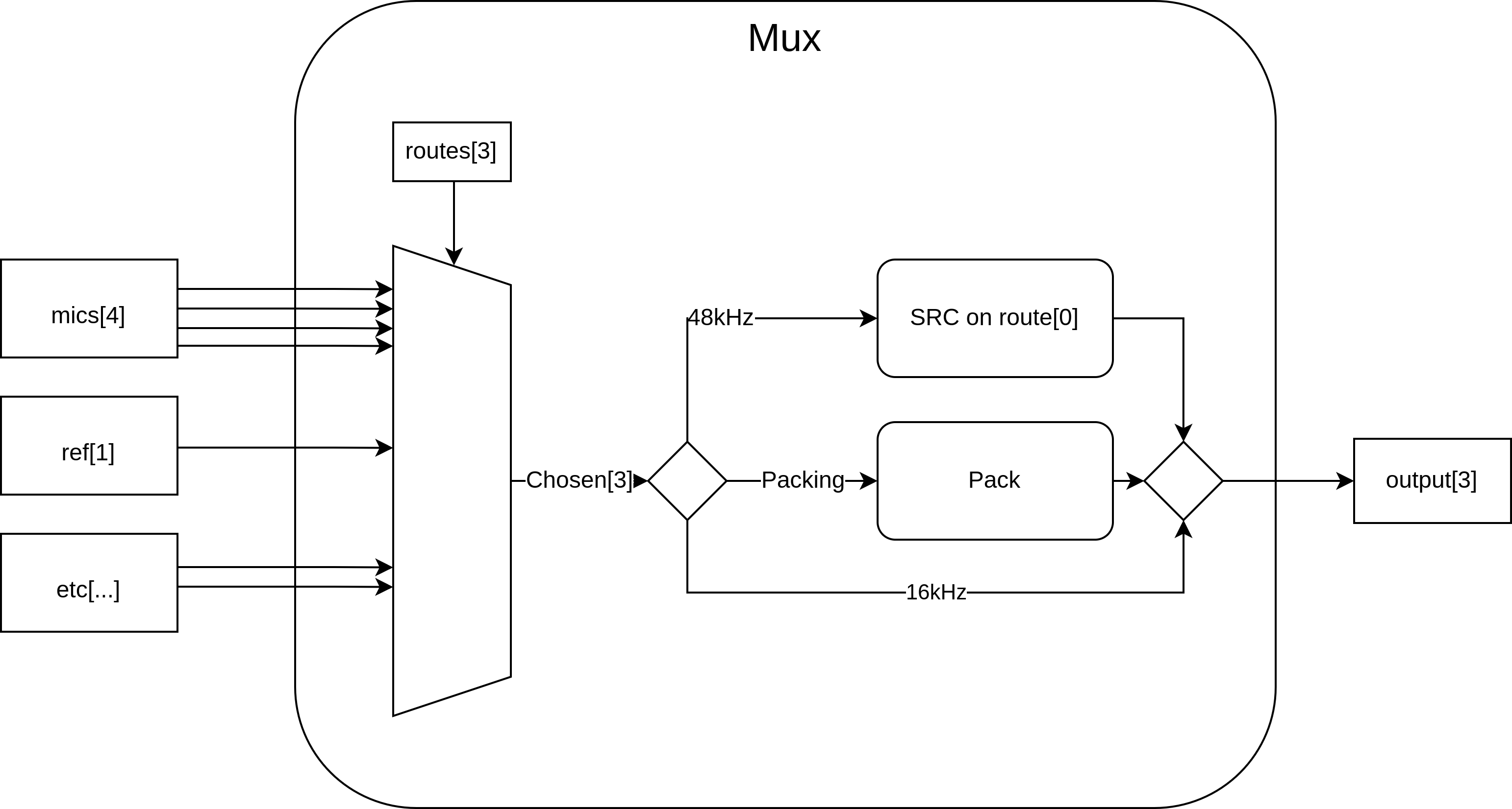
Fig. 35 Representation of a single output channel’s mux block#
The complete signal path of the XVF3800 is shown in Fig. 36. There are many useful signals which can be routed out of the device and the following sections provide some practical examples of using this capability for testing specific parts of the system.
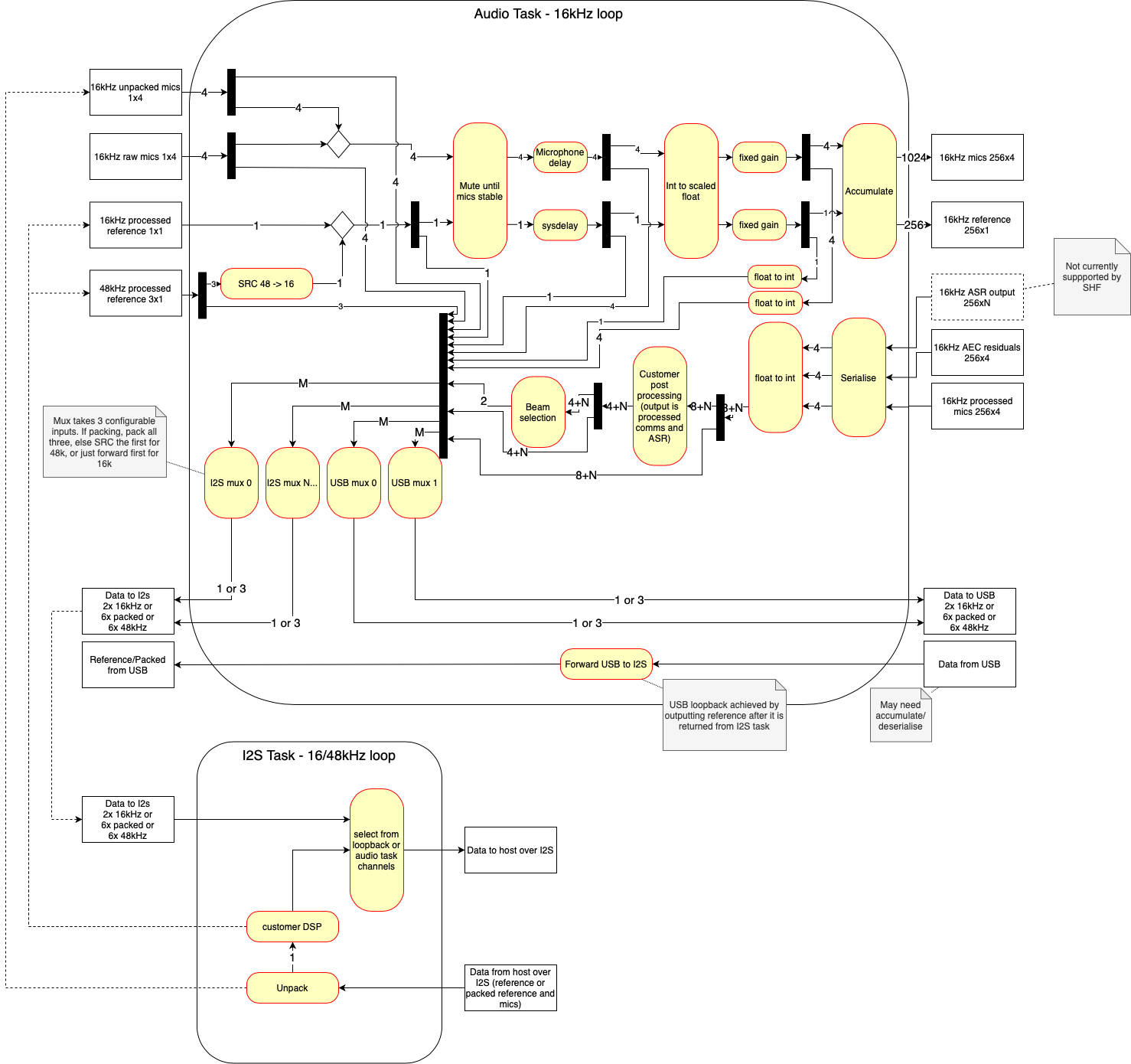
Fig. 36 Complete audio path through the XVF3800#
The User Guide provides additional details on the numerous signals available via the mux and how to translate the desired audio source into the enumerated value for passing to the host app.
Loopbacks#
When integrating the XVF3800 into the overall system it can be helpful to test signal path from and back to the host.
Note
All examples below assume a host rate of 48 kHz, which is 3x the voice-DSP rate.
This ‘round trip’ test is useful for validating the host->device and device->host paths at the same time. Normally, an audio stream provides the far-end reference, the mics provide the near-end and an audio output stream provides the processed microphone output.
In this example, the mux will be modified so that the far-end reference is looped back to the audio output stream. This can be useful for evaluating propagation delays and/or volume scaling within the complete system. The first command ensures that the native signal is used (instead of being down-sampled and then up-sampled) and the second command routes the raw far-end DSP signal to the output mux. Note that any far-end DSP used will be included in this signal path and so it can also be used to check its operation. See Modifying the Software for an example of adding far-end DSP.
./xvf_host AUDIO_MGR_OP_UPSAMPLE 0 0
./xvf_host AUDIO_MGR_OP_ALL 10 0 10 2 10 4 10 1 10 3 10 5
Another useful feature is to be able to capture the raw microphone signals and listen to them without passing them through the voice-DSP. This can be helpful when validating custom hardware to check that the microphones are properly connected and also evaluate the relative gain between them. This is useful for debugging when developing custom enclosures.
The first command ensures that up-sampling is used (if the host interface is different from the native microphone rate of 16 kHz) and the subsequent commands route the raw microphone signals to the output mux. Note that no microphone gain will be applied. The microphone front-end is tuned to support the acoustic overload point of the microphones without clipping and hence sounds quiet for normal listening without gain.
./xvf_host AUDIO_MGR_OP_UPSAMPLE 1 1
# Set the left output to raw mic 0 and the right output to raw mic 1
./xvf_host AUDIO_MGR_OP_L 1 0
./xvf_host AUDIO_MGR_OP_R 1 1
# Set the left output to raw mic 2 and the right output to raw mic 3
./xvf_host AUDIO_MGR_OP_L 1 2
./xvf_host AUDIO_MGR_OP_R 1 3
The amplified microphone signal (again without voice-DSP) is also available at the mux. This is helpful for tuning the system for the voice-DSP which is optimised for a certain microphone level.
./xvf_host AUDIO_MGR_OP_UPSAMPLE 1 1
# Set the left output to amplified mic 0 and the right output to amplified mic 1
./xvf_host AUDIO_MGR_OP_L 3 0
./xvf_host AUDIO_MGR_OP_R 3 1
# Set the left output to amplified mic 2 and the right output to amplified mic 3
./xvf_host AUDIO_MGR_OP_L 3 2
./xvf_host AUDIO_MGR_OP_R 3 3
The AEC residuals are also available at the mux. These signals are the output directly from the AEC and can be helpful for tuning other echo suppression functions such as non-linear echo and echo suppression.
./xvf_host AUDIO_MGR_OP_UPSAMPLE 1 1
# Set the left output to aec residuals of mic 0 and the right output to aec residuals of
# mic 1
./xvf_host AUDIO_MGR_OP_L 7 0
./xvf_host AUDIO_MGR_OP_R 7 1
# Set the left output to aec residuals of mic 2 and the right output to aec residuals of
# mic 3
./xvf_host AUDIO_MGR_OP_L 7 2
./xvf_host AUDIO_MGR_OP_R 7 3
Finally, it may useful to test the background noise of a system. The mux can also provide zero samples. The below commands show how to do this.
./xvf_host AUDIO_MGR_OP_UPSAMPLE 1 1
# Set the left and right outputs to silence
./xvf_host AUDIO_MGR_OP_L 0 0
./xvf_host AUDIO_MGR_OP_R 0 0
For instruction on capturing more than two signals at a time, please see the Signal Capture section.
Signal Capture#
It can be very useful to capture the entire voice-DSP pipeline input including the unprocessed mics and the far-end reference. This allows a test vector for a particular acoustic environment to be captured which can then be inspected or even processed offline, such as being run through a simulated or hardware voice-DSP processing system. Processing the same vector offline allows repeatable testing while tuning parameters for example, or even providing a test vector when requesting technical support. See the Signal Injection and Signal Injection and Capture Simultaneously sections for how to provide a test vector and re-use it in the system.
Note
All signal injection/capture features require the host audio rate to be running at 3x the voice-DSP rate. The reason for this is that the voice-DSP requires multiple channels (mics + reference) and the output is normally 2 channels. The multiple channels of the voice-DSP signals are packed into a stereo signal at one third the rate. Scripts are provided for packing/unpacking the signals.
To capture the voice-DSP pipeline input, use the following commands which capture the mono far-end signal (with delay and gain if enabled), the four amplified (and optionally delayed) raw-mic signals and the processed output (autoselect beam in this case):
# Enable packed output
./xvf_host AUDIO_MGR_OP_PACKED 1 1
# Set the 48 kHz stereo to output all 5 channels of input to the voice-DSP
./xvf_host AUDIO_MGR_OP_ALL 12 0  3 0  3 2  6 3  3 1  3 3
Next, the output signal may be recorded and unpacked to a channel wav file. The example below uses the Linux arecord utility to capture the signal on the raspberry Pi. It may be beneficial to invoke a background aplay instance to provide far-end audio before this is run:
# Play the desired far-end reference signal in the background
aplay <my_48kHz_stereo_far_end_reference_signal.wav> &
# Run a stereo audio capture at 48 kHz with 32b bit depth for 60 sec
arecord -r 48000 -f S32_LE -c 2 -d 60 <capture_48k_2ch.wav>
# Unpack the 48 kHz stereo packed file into a 6ch 16 kHz unpacked wav using 32b sample depth
./packing.py unpack <capture_48k_2ch.wav> <unpacked_16k_6ch.wav> -b 32
The file <capture_48k_2ch.wav> has been recorded at 48 kHz stereo and at the full bit width of I2S of 32b which includes the packing markers in the LSB. The output from the unpack operation is a 16 kHz, 6 channel signal with the following channel designation:
Channel 1 is the left far-end reference, post delay and amplification
Channel 2 is the processed output (autoselect beam)
Channel 3 is the amplified raw MIC 0, post delay
Channel 4 is the amplified raw MIC 1, post delay
Channel 5 is the amplified raw MIC 2, post delay
Channel 6 is the amplified raw MIC 3, post delay
An image of an example 6 channel unpacked captured wav can be seen in Fig. 37. The far-end reference can be seen playing and each of the mics (0..3) have been tapped in sequence to show a large noise source being captured.
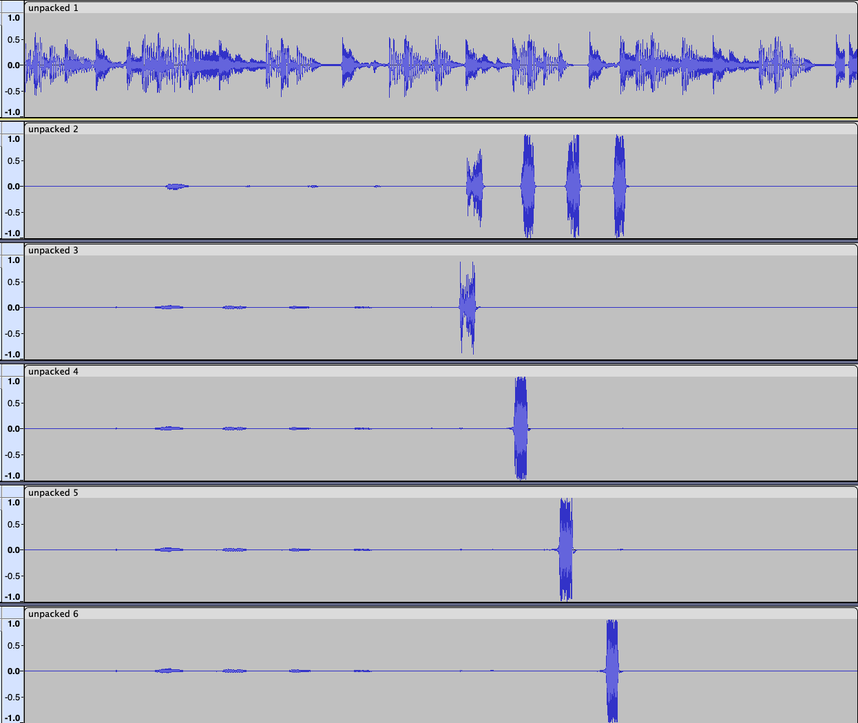
Fig. 37 Screenshot of the unpacked output from the XVF3800#
Since the packer needs chunks of three samples, it is likely that the first and last frame are not complete; this may cause the following warningm which means partial frames at the start and finish have been discarded. Discarding partial frames is important to ensure the remaining unpacked samples are correctly time aligned:
Warning: Bad indices: [[113999 0]]
If the following output is observed (with no output file generated), it means that either the audio mux in the XVF3800 has not been configured to properly produce a packed output, the sample resolution is incorrect or the capture process has been corrupted (perhaps by volume scaling). Re-check the mux configuration commands and host system controls.
Error: Over 50 markers incorrectly spaced so giving up.
Note
Signal packing uses LSB markers to encode the channel packing sequence. These are then stripped so do not contribute to noise. For 32b audio, the LSB is over 190 dB down from full scale and the loss of precision is insignificant. However it is critical to ensure that any volume controls are disabled (volume = 100%) to prevent the packed audio frame being corrupted.
Signal Injection#
The XVF3800 supports a mode where the input to DSP pipeline can be fed directly from a 5-channel test vector which may either be pre-generated or even pre-captured by recording directly from an XVF3800 device - see Signal Capture. This can be helpful when re-creating a previously seen scenario or when tuning the system via the control interface in the presence of a fixed and repeatable test vector.
Note
The XVF3800 contains a lot of state such as pre-learned AEC coefficients. When re-running a particular test vector it is important to ensure the device is reset, either by individually resetting the various blocks or alternatively by resetting the entire firmware using ./xvf_host TEST_CORE_BURN 0, which will force a reboot of the firmware from the host application.
The vector injection mode works by packing 6-channel 16 kHz input data (four microphones, a mono reference and an unused channel) into a 48 kHz stereo input signal. The device then unpacks the 48 kHz wav file into a 16 kHz multi-channel input and feeds it directly into the front end of the voice-DSP pipeline.
Note
It is essential to use a 48 kHz host audio rate for this process to work since the higher rate is needed to support channel packing.
The required format of the 6 channel test vector should be as follows:
Channel 1 is the far-end reference signal
Channel 2 is ignored
Channel 3 is the amplified raw MIC 0
Channel 4 is the amplified raw MIC 1
Channel 5 is the amplified raw MIC 2
Channel 6 is the amplified raw MIC 3
Suitable test vectors may be obtained directly from the XVF3800 using the Signal Capture procedure.
Next, turn the six channel 16 kHz test vector into a 48 kHz packed file:
# Pack the 6ch 16 kHz unpacked wav into a 48 kHz stereo file using 32b sample depth
./packing.py pack <my_6ch_vector.wav> <my_packed_vector.wav> -b 32
With the firmware freshly booted and running, configure the input to accept a packed signal:
# Configure I2S to unpack a 48 kHz packed input
./xvf_host I2S_INPUT_PACKED 1
# Set mic gain to 1.0. This is needed if the original vector is captured after amplifying
# raw mics; otherwise, skip this command
./xvf_host AUDIO_MGR_MIC_GAIN 1.0
With the firmware ready to run a packed input, now is a good time to perform any configuration via the control utility such as tweaking tuning parameters.
Finally, play the input vector. In this case a background arecord session has also been run to capture the output from the XVF3800 simultaneously.
# Run a stereo audio capture at 48 kHz with 32b bit depth in the background
arecord -r 48000 -f S32_LE -c 2 <test_output.wav> &
# Play the pre-packed test vector signal and terminate the recording when done
aplay <my_packed_vector.wav> && killall arecord
Listen to and inspect the output file, which contains the processed output from the input test vector.
Signal Injection and Capture Simultaneously#
Enabling multi-channel input and output at the same time allows a full hardware-in-the-loop (HIL) system with a high degree of repeatability and visibility, as represented in Fig. 38. Not only can the same test vector be repeatably run through the system but multiple outputs may be observed simultaneously from different parts of the system including:
The raw inputs to the voice-DSP to ensure correct transport and injection/capture.
The delayed mic/far-end inputs to check that the input to the AEC is causal (the far-end reference must arrive before the acoustically coupled echo).
The amplified mics to ensure that the microphone amplifier gain has been tuned correctly.
Multiple beam outputs to help determine which of the beams performs best in the desired application.
The AEC residual signals to determine how much to tune the post-processing stages to trade off echo cancellation versus double-talk performance
Processed far-end DSP to ensure that the far-end DSP is performing as expected.
…and many more
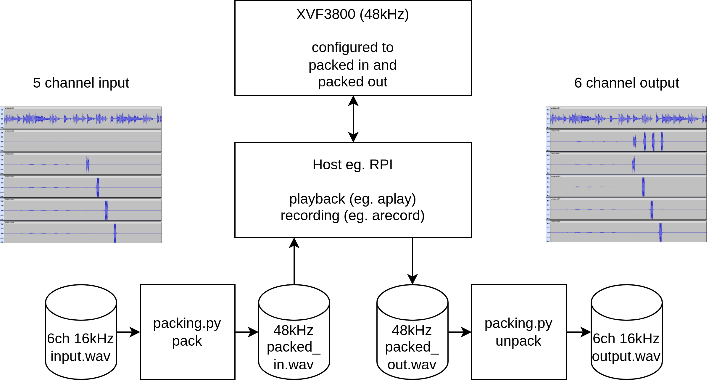
Fig. 38 Representation of a fully HIL workflow with the XVF3800#
An example of simultaneously injecting 5 channels of near and far-end whilst capturing the same 5 channels (plus the auto-select processed output) is shown below. For further details on the individual steps shown below, please consult the Signal Capture and Signal Injection sections above and be aware that resetting the firmware before each run is essential for consistency. See here for instructions on how to reset the firmware from the host app.
# Enable packed output
./xvf_host AUDIO_MGR_OP_PACKED 1 1
# Set the 48 kHz stereo to output all 5 channels of input to the voice-DSP
./xvf_host AUDIO_MGR_OP_ALL 5 0 3 0 3 2 6 3 3 1 3 3
# Configure I2S to unpack a 48 kHz packed input
./xvf_host I2S_INPUT_PACKED 1
# Set mic gain to 1.0. This is needed if the vector is capture after post-amplified raw
# mics; otherwise, skip this command
./xvf_host AUDIO_MGR_MIC_GAIN 1.0
# Pack the 6ch 16 kHz unpacked wav into a 48 kHz stereo file using 32b sample depth
./packing.py pack <my_6ch_vector.wav> <my_packed_vector.wav> -b 32

# Play the test vector in the background
aplay <my_packed_vector.wav> &
# Run a stereo audio capture at 48 kHz with 32b bit depth for 60 sec and stop the
# test_vector playback when done
arecord -r 48000 -f S32_LE -c 2 -d 60 <packed_capture.wav> && killall aplay

# Unpack the 48 kHz stereo packed file into a 6ch 16 kHz unpacked wav using 32b
# sample depth
./packing.py unpack <packed_capture.wav> <unpacked_capture.wav> -b 32
Measuring Resources#
In any embedded system, resources are limited and the XVF3800 is no exception. The main resources of concern are memory and processing cycles when adding additional source code. The methods for ensuring the application remains within the available resources are described in the following subsections.
Measuring Available Cycles#
Adding extra control code for initialising hardware, in general, has no effect on the real-time portion of the firmware thanks to the hardware scheduler and multiple logical cores of the XCORE. However, limited processing cycles are available to add user-DSP. Exceeding these limits will cause audio glitching or in some cases cause firmware instability.
Tools are provided, via the command interface, to allow quantifying of the number of cycles available and exercise the worst case timing case within the firmware. Exercising the worst case timing in the firmware and ensuring a non-zero number of processing cycles are still available is the best way to gain confidence that the code will always meet timing when deployed in the field under any operating conditions.
A number of control commands are available to assist with verifying that timing has not been violated. These commands report idle time, which is the amount of free time available within the audio loops. As this number approaches zero there is an increasing risk of violating timing. A basic command help string is available by executing ./xvf_host --list-commands. A more detailed description of the function of these commands can be seen below. Note that the TEST_CORE_BURN command is hidden from --list-commands since it is used only in test situations.
I2S idle times relate to far-end user DSP integration and audio manager idle times relate to output DSP integration. However, it is recommended to monitor both idle times since there is some interaction between these two tasks.
The commands in Table 29 provide information and control mechanisms relevant to achieving the necessary timing constraints.
Function |
Comment |
|---|---|
I2S_CURRENT_IDLE_TIME |
This command provides the current idle time of the last I2S loop executed in system timer ticks of 10 ns. This reports the real-time value and should only be used as an indication of how much the processing varies. Note that the amount of idle time heavily depends on the frequency of the I2S interface. For example, a 16 kHz I2S interface will offer significantly more idle time than the 48 kHz setting due to a 3x shorter cycle. |
I2S_MIN_IDLE_TIME |
This command provides the minimum idle time of all I2S loops executed in system timer ticks of 10 ns. This reports the worst case value since boot or since the idle time metric was last reset. It is the value that should be used to close timing when adding DSP. |
I2S_RESET_MIN_IDLE_TIME |
Use this control to reset the minimum idle time. |
AUDIO_MGR_CURRENT _IDLE_TIME |
This command provides the current idle time of the last audio manager loop executed in system timer ticks of 10 ns. This reports the real-time value and should only be used as an indication of how much the processing varies. |
AUDIO_MGR_MIN _IDLE_TIME |
This command provides the minimum idle time of all audio manager loops executed in system timer ticks of 10 ns. This reports the worst case value since the idle time metric was last reset. It is the value that should be used to close timing when adding DSP. |
AUDIO_MGR_RESET_MIN _IDLE_TIME |
Use this control to reset the minimum idle time. |
SHF_BYPASS |
The bypass command causes the far-field voice pipeline to be bypassed and the raw (but amplified) microphone signals to be passed to the output. In addition, it adds poll loops to burn processor cycles up to the maximum available for the voice pipeline section of the design. This means it exercises a tougher timing case compared with running the normal voice-DSP operation and so should be used when ascertaining the worst-case. |
TEST_CORE_BURN |
This hidden command places the firmware in ‘burn’ mode. Note this resets the firmware and consequently subsequent commands may be ignored while the firmware initialises. Because it performs a reset, all previously written parameters will be lost and all internal state will be set to the defaults that would be expected following power-on-reset. For this reason, it is recommended that this command be executed at the beginning of the timing-closure session. |
Note
The TEST_CORE_BURN command ensures all idle cycles in other parts of the XVF3800 are used up by creating polling loops. This significantly increases core power consumption of the XVF3800 when set to 1 (enable core burn). Expect increased power consumption of up to double the normal operating value when this test mode is used.
This means a typical sequence of commands to ascertain worst-case timing would be:
# Switch on burn mode and reboot the device. Wait at least 2 seconds before the next
# command to allow reboot time.
./xvf_host TEST_CORE_BURN 1
sleep(2)
# Bypass the voice-DSP and exercise worst case timing of the voice pipeline
./xvf_host SHF_BYPASS 1

# Allow the application to run for a while. Try restarting I2S a few times.
for i in {0..10}; do arecord -r 48000 -f S32_LE -c 2 -d 1 /dev/null; sleep 0.5; done

# Read the I2S minimum idle time (important if doing far-end DSP)
./xvf_host I2S_MIN_IDLE_TIME
# Read the audio manager minimum idle time (important if doing post voice-pipeline DSP)
./xvf_host AUDIO_MGR_MIN_IDLE_TIME


# Enable the voice-DSP and reset the minimum idle times
./xvf_host SHF_BYPASS 0
./xvf_host I2S_RESET_MIN_IDLE_TIME 1
./xvf_host AUDIO_MGR_RESET_MIN_IDLE_TIME 1

# Allow the application to run for a while. Try restarting I2S a few times.
for i in {0..10}; do arecord -r 48000 -f S32_LE -c 2 -d 1 /dev/null; sleep 0.5; done


# Read the I2S minimum idle time (important if doing far-end DSP)
./xvf_host I2S_MIN_IDLE_TIME
# Read the audio manager minimum idle time (important if doing post voice-pipeline DSP)
./xvf_host AUDIO_MGR_MIN_IDLE_TIME
Always use the smallest minimum idle times noted in the previous steps as a guide to how many cycles remain to ensure that the worst case has been covered. Always start and stop I2S a few times (10 times is enough) too, if possible, as this will further exercise the timing paths. If at any point the number of available cycles becomes close to zero, then the code exceeds the time slot available and it will be necessary to either optimise the DSP code to meet timing or reduce the amount of processing required.
Measuring Available Memory#
When building the software, the makefile settings are configured to produce a memory report which is printed at the end of the build. This report is statically generated by the compiler to precisely account for all of the memory used by the firmware. The firmware runs on two XCORE tiles, each with its own on-chip memory and consequently its own report. The majority of user configuration when modifying the software, such as adding hardware configuration code and user-DSP, will take place on tile[1] and so this is generally the number that will normally decrease with added functionality.
Note
The compiler builds the entire application twice due to the need to build the FreeRTOS kernel twice, once for each tile. This means that the compiler generates two memory constraints reports. In all cases, use the highest number number of the two reports as shown below.
The report shown below (with irrelevant lines deleted for clarity) shows a typical report for the application_xvf3800_intdev-lr48-lin-i2c firmware. Note that the precise memory usage varies considerably depending on the actual build, firmware version and the code that may have been added:
Constraint check for tile[0]:
Memory available:       524288,   used:       6980 .  OKAY
(Stack: 356, Code: 4064, Data: 2560)
Constraints checks PASSED.
Constraint check for tile[0]:
Memory available:       524288,   used:      491112 .  OKAY
(Stack: 10068, Code: 358940, Data: 122104)
Constraints checks PASSED WITH CAVEATS.
Constraint check for tile[1]:
Memory available:       524288,   used:      487908 .  OKAY
(Stack: 8340, Code: 397580, Data: 81988)
Constraints checks PASSED WITH CAVEATS.
Constraint check for tile[1]:
Memory available:       524288,   used:       6324 .  OKAY
(Stack: 356, Code: 3520, Data: 2448)
Constraints checks PASSED
Ignoring the lower numbers reported, in this case Tile[0] is using 491112 of 524288 bytes available and Tile[1] is using 487908 of 524288 bytes available. Therefore the free memory available is:
Tile[0]: 524288 - 491112 = 33176 Bytes
Tile[1]: 524288 - 487908 = 36380 Bytes
If usage exceeds the available memory the link stage of compilation will fail and the compiler will issue a clear error. In this case, reduce the memory usage.