Host Integration#
This example design can be integrated with existing solutions or modified to be a single controller solution.
Out of the Box Integration#
Out of the box integration varies based on configuration.
INT requires I2S connections to the host. Refer to the schematic, connecting the host reference audio playback to the ADC I2S and the host input audio to the DAC I2S. Out of the box, the INT configuration requires an externally generated MCLK of 12.288 MHz. 24.576 MHz is also supported and can be changed via the compile option MIC_ARRAY_CONFIG_MCLK_FREQ, found in ffva_int.cmake.
UA requires a USB connection to the host.
Support for ASR engine#
The example_ffva_int_cyberon_fixed_delay provides an example about how to include an ASR engine, the Cyberon DSPotter™.
Most of the considerations made in the section about the FFD devices are still valid for the FFVA example. The only notable difference is that the pipeline output in the FFVA example is on the same tile as the ASR engine, i.e. tile 0.
Note
Both the audio pipeline and the ASR engine process use the same sample block length. appconfINTENT_SAMPLE_BLOCK_LENGTH and appconfAUDIO_PIPELINE_FRAME_ADVANCE are both 240.
More information about the Cyberon engine can be found in Speech Recognition - Cyberon section.
Design Architecture#
The application consists of a PDM microphone input which is fed through the XMOS-VOICE DSP blocks. The output ASR channel is then output over I2S or USB.

Device Firmware update (DFU) Design#
The Device Firmware Update (DFU) allows updating the firmware of the device from a host computer, and it can be performed over I2C or USB. This interface closely follows the principles set out in version 1.1 of the Universal Serial Bus Device Class Specification for Device Firmware Upgrade, including implementing the state machine and command structure described there.
The DFU process is internally managed by the DFU controller module within the firmware. This module is tasked with overseeing the DFU state machine and executing DFU operations. The list of states and transactions are represented in the diagram in Fig. 1.
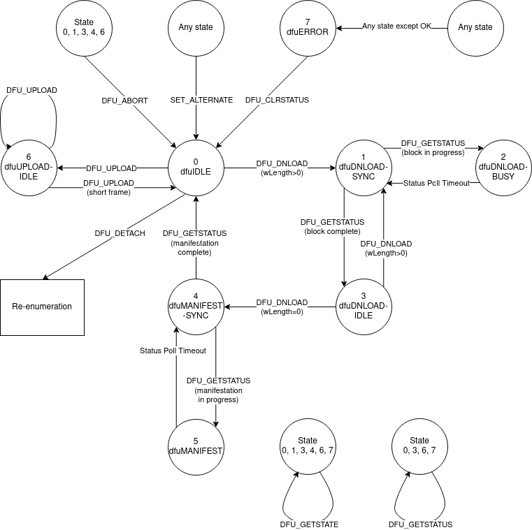
Fig. 1 State diagram of the DFU operations#
The main differences with the state diagram in version 1.1 of Universal Serial Bus Device Class Specification for Device Firmware Upgrade are:
the
appIDLEandappDETACHstates are not implemented, and the device is started in thedfuIDLEstatethe device goes into the
dfuIDLEstate when aSET_ALTERNATEmessage is receivedthe device is rebooted when a
DFU_DETACHcommand is received.
The DFU allows the following operations:
download of an upgrade image to the device
upload of factory and upgrade images from the device
reboot of the device.
The rest of this section describes the message sequence charts of the supported operations.
A message sequence chart of the download operation is below:
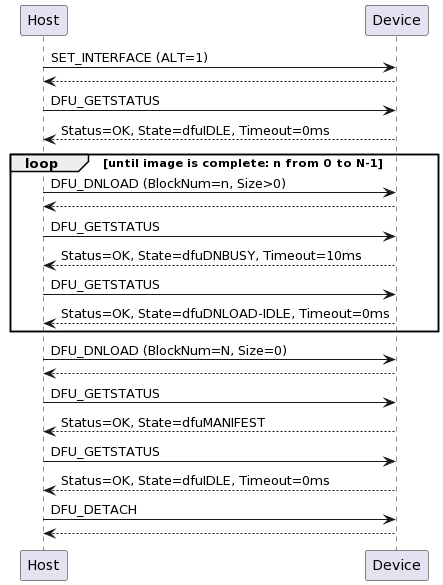
Fig. 2 Message sequence chart of the download operation#
Note
The end of the image transfer is indicated by a DFU_DNLOAD message of size 0.
Note
The DFU_DETACH message is used to trigger the reboot.
Note
For the I2C implementation, specification of the block number in download is not supported; all downloads must start with block number 0 and must be run to completion. The device will track this progress internally.
A message sequence chart of the reboot operation is below:
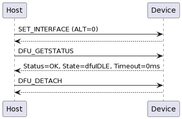
Fig. 3 Message sequence chart of the reboot operation#
Note
The DFU_DETACH message is used to trigger the reboot.
A message sequence chart of the upload operation is below:
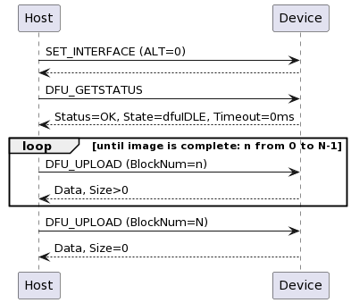
Fig. 4 Message sequence chart of the upload operation#
Note
The end of the image transfer is indicated by a DFU_UPLOAD message of size less than the transport medium maximum; this is 4096 bytes in UA and 128 bytes in INT.
DFU over USB implementation#
The UA variant of the device makes use of a USB connection for handling DFU operations. This interface is a relatively standard, specification-compliant implementation. The implementation is encapsulated within the tinyUSB library, which provides a USB stack for the sln_voice.
DFU over I2C implementation#
The INT variant of the device presents a DFU interface that may be controlled over I2C.
Fig. 5 shows the modules involved in processing the DFU commands. The I2C task has a dedicated logical core so that it is always ready to receive and send control messages. The DFU state machine is driven by the control commands. The DFU state machine interacts with a separate RTOS task in order to asynchronously perform flash read/write operations.
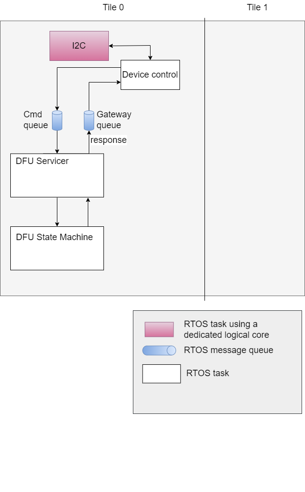
Fig. 5 sln_voice Control Plane Components Diagram#
Fig. 6 shows the interaction between the Device Control module and the DFU Servicer. In this diagram, boxes with the same colour reside in the same RTOS task.
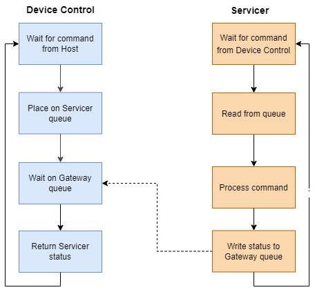
Fig. 6 sln_voice Device Control – Servicer Flow Chart#
This diagram shows a critical aspect of the DFU control operation. The Device Control module, having placed a command on a Servicer’s command queue, waits on the Gateway queue for a response. As a result, it ensures processing of a single control command at a time. Limiting DFU control operation to a single command in-flight reduces the complexity of the control protocol and eliminates several potential error cases.
The FFVA-INT uses a packet protocol to receive control commands and send each corresponding response. Because packet transmission occurs over a very short-haul transport, as in I2C, the protocol does not include fields for error detection or correction such as start-of-frame and end-of-frame symbols, a cyclical redundancy check or an error correcting code. Fig. 7 depicts the structure of each packet.

Fig. 7 sln_voice Control Plane Packet Diagram#
Packets containing a response from the FFVA-INT to the host application place a status value in the first byte of the payload.
Mirroring the USB DFU specification, the INT DFU implementation supports a set of 9 control commands intended to drive the state machine, along with an additional 2 utility commands:
Name |
ID |
Length |
Payload Structure |
Purpose |
|---|---|---|---|---|
DFU_DETACH |
0 |
1 |
Payload unused |
Write-only command. Restarts the device. Payload is required for protocol, but is discarded within the device. This command has a defined purpose in the USB DFU specification, but in a deviation to that specification it is used with I2C simply to reboot the device. Future versions of the XMOS DFU-by-device-control protocol (but not future versions of this product) may choose to alter the function of this command to more closely align with the USB DFU specification. |
DFU_DNLOAD |
1 |
130 |
2 bytes length marker, followed by 128 bytes of data buffer |
Write-only command. The first two bytes indicate how many bytes of data are being transmitted in this packet. These bytes are little-endian, so byte 0 represents the low byte and byte 1 represents the high byte of an unsigned 16b integer. The remaining 128 bytes are a data buffer for transfer to the device. All control command packets are a fixed length, and therefore all 128 bytes must be included in the command, even if unused. For example, a payload with length of 100 should have the first 100 bytes of data set, but must send an additional 28 bytes of arbitrary data. |
DFU_UPLOAD |
2 |
130 |
2 bytes length marker, followed by 128 bytes of data buffer |
Read-only command. The first two bytes indicate how many bytes of data are being transmitted in this packet. These bytes are little-endian, so byte 0 represents the low byte and byte 1 represents the high byte of an unsigned 16b integer. The remaining 128 bytes are a data buffer of data received from the device. All control command packets are a fixed length, and therefore this buffer will be padded to length 128 by the device before transmission. The device will, as per the USB DFU specification, mark the end of the upload process by sending a “short frame” - a packet with a length marker less than 128 bytes. |
DFU_GETSTATUS |
3 |
5 |
1 byte representing device status, 3 bytes representing the requested timeout, 1 byte representing the next device state. |
Read-only command. The first byte returns the device status code, as described in the USB DFU specification in the table in section 6.1.2. The next 3 bytes represent the amount of time the host should wait, in ms, before issuing any other commands. This timeout is used in the DNLOAD process to allow the device time to write to flash. This value is little-endian, so bytes 1, 2, and 3 represent the low, middle, and high bytes respectively of an unsigned 24b integer. The final byte returns the number of the state that the device will move into immediately following the return of this request, as described in the USB DFU specification in the table in section 6.1.2. |
DFU_CLRSTATUS |
4 |
1 |
Payload unused |
Write-only command. Moves the device out of state 10, dfuERROR. Payload is required for protocol, but is discarded within the device. |
DFU_GETSTATE |
5 |
1 |
1 byte representing current device state. |
Read-only command. The first (and only) byte represents the number of the state that the device is currently in, as described in the USB DFU specification in the table in section 6.1.2. |
DFU_ABORT |
6 |
1 |
Payload unused |
Write-only command. Aborts an ongoing upload or download process. Payload is required for protocol, but is discarded within the device. |
DFU_SETALTERNATE |
64 |
1 |
1 byte representing either factory (0) or upgrade (1) DFU target images |
Write-only command. Sets which of the factory or upgrade images should be targeted by any subsequent upload or download commands. Use of this command entirely resets the DFU state machine to initial conditions: the device will move to dfuIDLE, clear all error conditions, wipe all internal DFU data buffers, and reset all other DFU state apart from the DFU_TRANSFERBLOCK value. This command is included to emulate the SET_ALTERNATE request available in USB. |
DFU_TRANSFERBLOCK |
65 |
2 |
2 bytes, representing the target transfer block for an upload process. |
Read/write command. Sets/gets a 2 byte value specifying the transfer block number to use for a subsequent upload operation. A complete image may be conceptually divided into 128-byte blocks. These blocks may then be numbered from 0 upwards. Setting this value sets which block will be returned by a subsequent DFU_UPLOAD request. This value is initialised to 0, and autoincrements after each successful DFU_UPLOAD request has been serviced. Therefore, to read a whole image from the start, there is no need to issue this command - this command need only be used to select a specific section to read. Because this value is automatically incremented after a DFU_UPLOAD command is successfully serviced, reading it will give the value of the next block to be read (and this will be one greater than the previous block read, if it has not been altered in the interim). This value is reset to 0 at the successful completion of a DFU_UPLOAD process. It is not reset after a DFU_ABORT, nor after a DFU_SETALTERNATE call. This command is included to emulate the ability in a USB request to send values in the header of the request - the device control protocol used here does not allow sending any data with a read request such as DFU_UPLOAD. |
DFU_GETVERSION |
88 |
3 |
3 bytes, representing major.minor.patch version of device |
Read-only command. Bytes 0, 1, and 2 represent the major, minor, and patch versions respectively of the device. This is a utility command intended to provide an easy mechanism by which to verify that a firmware download has been successful. |
DFU_REBOOT |
89 |
1 |
Payload unused |
Write-only command. Restarts the device. Payload is required for protocol, but is discarded within the device. This is a utility command intended to provide a clear and unambiguous interface for restarting the device. Use of this command should be preferred over DFU_DETACH for this purpose. |
These commands are then used to drive the state machine described in the Device Firmware update (DFU) Design.
When writing a custom compliant host application, the use of XMOS’ fwk_rtos library is advised; the device_control library provided there gives a host API that can communicate effectively with the FFVA-INT. A description of the I2C bus activity during the execution of the above DFU commands is provided below, in the instance that usage of the device_control library is inconvenient or impossible.
The FFVA-INT I2C address is set by default as 0x42. This may be
confirmed by examination of the appconf_CONTROL_I2C_DEVICE_ADDR define in the
platform_conf.h file. The I2C address may also be altered by editing this file.
The DFU resource has an internal “resource ID” of 0xF0. This maps to the
register that read/write operations on the DFU resource should target -
therefore, the register to write to will always be 0xF0.
To issue a write command (e.g. DFU_SETALTERNATE):
First, set up a write to the device address. For a default device configuration, a write operation will always start by a write token to 0x42 (START, 7 bits of address [0x42], R/W bit [0 to specify write]), wait for ACK, followed by specifying the register to write [Resource ID 0xF0] (and again wait for ACK).
Then, write the command ID (in this example, 64 [0x40]) from the above table.
Then, write the total transfer size, including the register byte. In this example, that will be 4 bytes (register byte, command ID, length byte, and 1 byte of payload), so write 0x04.
Finally, send the payload - e.g. 1 to set the alternate setting to “upgrade”.
The full sequence for this write command will therefore be START, 7 bits of address [0x42], 0 (to specify write), hold for ACK, 0xF0, hold for ACK, 0x40, hold for ACK, 0x04, hold for ACK, 0x01, hold for ACK, STOP.
To complete the transaction, the device must then be queried; set up a read to 0x42 (START, 7 bits of address [0x42], R/W bit [1 to specify read], wait for ACK). The device will clock-stretch until it is ready, at which point it will release the clock and transmit one byte of status information. This will be a value from the enum
control_ret_tfromdevice_control_shared.h, found inmodules\rtos\modules\sw_services\device_control\api.
To issue a read command (e.g. DFU_GETSTATUS):
Set up a write to the device; as above, this will mean sending START, 7 bits of device address [0x42], 0 (to specify write), hold for ACK. Send the DFU resource ID [0xF0], hold for ACK.
Then, write the command ID (in this example, 3), bitwise ANDed with 0x80 (to specify this as a read command) - in this example therefore 0x83 should be sent, and hold for ACK.
Then, write the total length of the expected reply. In this example, the command has a payload of 5 bytes. The device will also prepend the payload with a status byte. Therefore, the expected reply length will be 6 bytes [0x06]. Hold for ACK.
Then, issue a repeated START. Follow this with a read from the device: the repeated START, 7 bits of device address [0x42], 1 (to specify read), hold for ACK. The device will clock-stretch until it is ready. It will then send a status byte (from the enum
control_ret_tas described above), followed by a payload of requested data - in this example, the device will send 5 bytes. ACK each received byte. After the last expected byte, issue a STOP.
It is heavily advised that those wishing to write a custom host application to drive the DFU process for the FFVA-INT over I2C familiarise themselves with version 1.1 of the Universal Serial Bus Device Class Specification for Device Firmware Upgrade.