Designing a sliceCARD
Power
sliceCARDs have two power supplies available to them, 5V and 3V3. The 5V supply can range from 4.75V to 5.25V (5%) at a current of up to 0.25A per slice. The 3V3 supply can range from 3.13V to 3.47V (5%) at a current of up to 0.25A per slice.
Signal I/O
A single sliceCARD connector has 36 contacts. The four types of slice have a number of common pins which are described below.
- GND: Power supply ground.
- 5V: 5V power supply input.
- 3V3: 3.3V power supply input.
- NC: Not connected.
- CLK: System clock input, 25MHz.
- RST_N: System reset input, active low. Push-pull drive.
The other available pins are connected to xCORE processor I/Os as shown in the pinout tables.
sliceCARDs can take their power from either 5V or 3V3 or both, but they should draw no more than 250mA from each supply.
At system power-on, the 5V supply will power up first, followed by the 3V3 supply. The system reset signal will de-assert a short time after this.
Due to the constraints on the sliceKIT core board, there are some ports on the sliceCARDs which should be used in preference to others. These constraints are as follows:
- X0D4-7 can be selected for use as the xSCOPE xCONNECT Link
- X1D40-43 are not available on the L16 device
- X0D0,1,10,11 could be used for SPI boot on a master core board. These pins will be hi-z when booting and can be transferred to the xCORE I/O signals when boot is complete.
For sliceCARDs intended for use in the Star slot, P4B should be avoided with the knowledge that using it means xSCOPE cannot be used if the sliceCARD is plugged into the Star slot.
sliceCARD form factors
The sliceCARDs use a standard PCIe x1 edge finger to connect to the sliceKIT core board. Because of this, all sliceCARD PCBs must be 1.6mm thick.
There is no hard specification as to the length of sliceCARDs as this poses no mechanical clashing hazard, however to avoid clashing with other sliceCARDs or the power input connector, sliceCARDs should be limited to 40mm wide.
Four mounting holes are specified in the corners of the slice for mechanical stability. These should be used with 6mm standoffs, example part Toby Electronics DCB-6.
An optional retention hole is specified for use in securing the sliceCARD to the sliceKIT core board. This is useful to ensure the sliceCARDs is not accidentally unplugged when using the system. Typical usage uses a 2.54mm cable tie between this hole and the associated hole in the sliceKIT core board ensuring the sliceCARD cannot be unplugged.
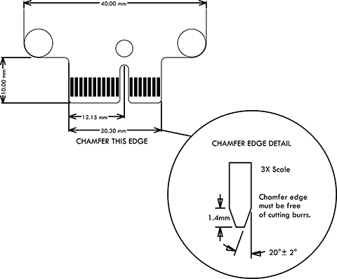
Note that for quick, low cost boards using low cost PCB manufacturing, the chamfer is not required and can be generated by hand using a file or similar.
Connector pinouts
The pinouts of the four types of sliceCARD are shown below. To cross reference pin numbers (e.g. X0D1) to port names, see here:
STAR
PIN |
SIDE B (top) |
SIDE A (bottom) |
|---|---|---|
1 |
NC |
NC |
2 |
NC |
5V |
3 |
GND |
NC |
4 |
NC |
NC |
5 |
3V3 |
GND |
6 |
X0D2 |
X0D8 |
7 |
X0D3 |
X0D9 |
8 |
GND |
X0D1 |
9 |
X0D4 |
X0D6 |
10 |
X0D10 |
GND |
11 |
X0D3 |
X0D7 |
MECHANICAL KEY |
||
12 |
X0D14 |
X0D20 |
13 |
X0D15 |
X0D21 |
14 |
CLK |
GND |
15 |
X0D22 |
X0D13 |
16 |
GND |
RST_N |
17 |
X0D16 |
X0D18 |
18 |
X0D17 |
X0D19 |
SQUARE
PIN |
SIDE B (top) |
SIDE A (bottom) |
|---|---|---|
1 |
DEBUG |
MSEL |
2 |
TCK |
5V |
3 |
GND |
TMS |
4 |
TDI |
TDO |
5 |
3V3 |
PRSNT |
6 |
X1D2 |
X1D8 |
7 |
X1D3 |
X1D9 |
8 |
GND |
X1D1 |
9 |
X1D4 |
X1D6 |
10 |
X1D10 |
GND |
11 |
X1D3 |
X1D7 |
MECHANICAL KEY |
||
12 |
X1D14 |
X1D20 |
13 |
X1D15 |
X1D21 |
14 |
CLK |
GND |
15 |
X1D22 |
X1D13 |
16 |
GND |
RST_N |
17 |
X1D16 |
X1D18 |
18 |
X1D17 |
X1D19 |
TRIANGLE
PIN |
SIDE B (top) |
SIDE A (bottom) |
|---|---|---|
1 |
NC |
NC |
2 |
X0D0 |
5V |
3 |
GND |
X0D12 |
4 |
X0D11 |
X0D23 |
5 |
3V3 |
GND |
6 |
X0D26 |
X0D32 |
7 |
X0D27 |
X0D33 |
8 |
GND |
X0D25 |
9 |
X0D28 |
X0D30 |
10 |
X0D34 |
GND |
11 |
X0D29 |
X0D31 |
MECHANICAL KEY |
||
12 |
X0D36 |
X0D42 |
13 |
X0D37 |
X0D43 |
14 |
CLK |
GND |
15 |
X0D24 |
X0D35 |
16 |
GND |
RST_N |
17 |
X0D38 |
X0D40 |
18 |
X0D39 |
X0D41 |
CIRCLE
PIN |
SIDE B (top) |
SIDE A (bottom) |
|---|---|---|
1 |
NC |
NC |
2 |
X1D0 |
5V |
3 |
GND |
X1D12 |
4 |
X1D11 |
X1D23 |
5 |
3V3 |
GND |
6 |
X1D26 |
X1D32 |
7 |
X1D27 |
X1D33 |
8 |
GND |
X1D25 |
9 |
X1D28 |
X1D30 |
10 |
X1D34 |
GND |
11 |
X1D29 |
X1D31 |
MECHANICAL KEY |
||
12 |
X1D36 |
NC |
13 |
X1D37 |
NC |
14 |
CLK |
GND |
15 |
X1D24 |
X1D35 |
16 |
GND |
RST_N |
17 |
X1D38 |
NC |
18 |
X1D39 |
NC |