sliceKIT overview
Introduction
This document covers the hardware design of the sliceKIT Modular Development System, consisting of the core board, sliceCARDs and xSYS adaptor.
The core board contains a fully pinned out 16-core xCORE multicore microcontroller. All GPIOs are connected to four expansion connectors (termed slots) which interface with expansion cards called sliceCARDs that plug into the slots. The core board also contains all circuitry necessary for operating and debugging the xCORE system. Multiple sliceKIT core boards can be interconnected to form a multi xCORE device system with dual 5-bit xCONNECT Links being present between the boards.
sliceKIT system layout
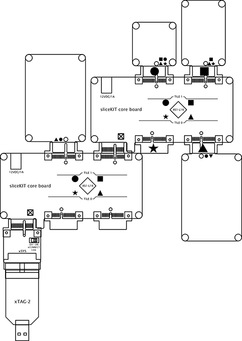
The diagram above shows an overview of the layout of the core board with sliceCARDs attached. Each of the four slots has a specific label - Star, Triange, Square, Circle printed on the core board silkscreen. Triangle and Circle sliceCARDs contain 24 xCORE I/Os, and the Star and Square sliceCARDs have 20 xCORE I/Os (usable as GPIO or two 5-wire xCONNECT links). The label denotes which sliceCARDs are compatible with which core board slots. The sliceCARDs are also marked with one or more of these labels to identify the slot type(s) they function correctly with.
The final type of connector is on the bottom left of the core board and is marked with a hollow square symbol with an X through it. This is for connecting multiple core boards together to form systems of 32 logical cores or more. It is termed the chain slot.
All slots are 36 pin PCI express style connectors in either socket or edge finger (plug) types.
Star and Triangle slots are pinned out from Tile 0 of the XS1-L16 xCORE device and the Circle and Square slots from Tile 1.