The xcore.ai Multi-Channel Audio Board
An application of the USB audio framework is provided specifically for the XK_AUDIO_316_MC
hardware described in USB Audio hardware platforms and is implemented on an xcore.ai
series dual tile device. The related code can be found in app_usb_aud_xk_316_mc.
The design supports upto 8 channels of analogue audio input/output at sample-rates up to 192 kHz
(assuming the use of I²S). This can be further increased by utilising TDM. It also supports S/PDIF,
ADAT and MIDI input and output as well as the mixing functionalty of lib_xua.
The design uses the following tasks:
XMOS USB Device Driver (XUD)
Endpoint 0
Endpoint Buffer
Decoupler
AudioHub Driver
Mixer
S/PDIF Transmitter
S/PDIF Receiver
ADAT Transmitter
ADAT Receiver
Clockgen
MIDI
The software layout of the USB Audio 2.0 Reference Design running on the xcore.ai device is shown in Fig. 1.
Each circle depicts a task running in a single core concurrently with the other tasks. The lines show the communication between each task.
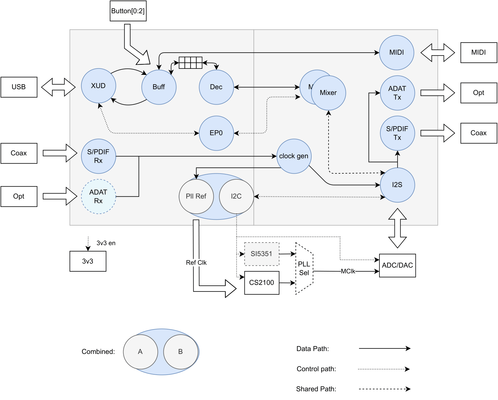
Fig. 1 xcore.ai multichannel audio system/task diagram
Audio hardware
Clocking and clock selection
As well as the secondary (application) PLL of the xcore.ai device the board includes two options for master clock generation:
A Cirrus Logic CS2100 fractional-N clock multiplier allowing the master clock to be generated from a xcore derived reference clock.
A Skyworks Si5351A-B-GT CMOS clock generator.
The master clock source is chosen by driving two control signals as shown below:
Control Signal |
Master Clock Source |
|
|---|---|---|
EXT_PLL_SEL |
MCLK_DIR |
|
0 |
0 |
Cirrus CS2100 |
1 |
0 |
Skyworks SI5351A-B-GT |
X |
1 |
xcore.ai secondary (application) PLL |
Each of the sources have potential benefits, some of which are discussed below:
The Cirrus CS2100 simplifies generating a master clock locked to an external clock (such as S/PDIF in or word clock in).
It multiplies up the PLL_SYNC signal which is generated by the xcore.ai device based on the desired external source (so S/PDIF in frame signal or word clock in).
The Si5351A-B-GT offers very low jitter performance at a relatively lower cost than the CS2100. Locking to an external source is more difficult.
The xcore.ai secondary PLL is obviously the lowest cost and significantly lowest power solution, however its jitter performance can not match the Si5351A which may be important in demanding applications. Locking to an external clock is possible but involves more complicated firmware and more MIPS.
The master clock source is controlled by a mux which, in turn, is controlled by bit 5 of PORT 8C:
Value |
Source |
|---|---|
0 |
Master clock is sourced from PhaseLink PLL |
1 |
Master clock is source from Cirrus Clock Multiplier |
The clock-select from the phaselink part is controlled via bit 7 of PORT 8C:
Value |
Frequency |
|---|---|
0 |
24.576MHz |
1 |
22.579MHz |
DAC and ADC
The board is equipped with four PCM5122 stereo DACs from Texas instruments and two quad-channel PCM1865 ADCs from Texas Instruments, giving 8 channels of analogue output and 8 channels of analogue input. Configuration of both the DAC and the ADC takes place over I²C.
Configuring audio hardware
All of the external audio hardware is configured using lib_board_support.
Note
lib_board_support has the I²C library (lib_i2c) in its dependency list.
The hardware targeted is the XMOS XU316 Multichannel Audio board (XK-AUDIO-316-MC).
The lib_board_support functions xk_audio_316_mc_ab_board_setup(), xk_audio_316_mc_ab_i2c_master(),
xk_audio_316_mc_ab_AudioHwInit() and xk_audio_316_mc_ab_AudioHwConfig() are called at various points during initialisation and
runtime to start the I²C master, to initialise and configure the audio hardware.
The audio hardware configuration is set in the config structure of type xk_audio_316_mc_ab_config_t which is passed to the xk_audio_316_mc_ab_board_setup(),
xk_audio_316_mc_ab_AudioHwInit() and xk_audio_316_mc_ab_AudioHwConfig() functions.
static xk_audio_316_mc_ab_config_t config =
{
    // clk_mode
    (XUA_SYNCMODE == XUA_SYNCMODE_SYNC || XUA_SPDIF_RX_EN || XUA_ADAT_RX_EN)
    ? ( XUA_USE_SW_PLL
        ? CLK_PLL : CLK_CS2100 )
    : CLK_FIXED,

    // dac_is_clk_master
    CODEC_MASTER,

    // default_mclk
    (DEFAULT_FREQ % 22050 == 0) ? MCLK_441 : MCLK_48,

    // pll_sync_freq
    PLL_SYNC_FREQ,

    // pcm_format
    XUA_PCM_FORMAT,

    // i2s_n_bits
    XUA_I2S_N_BITS,

    // i2s_chans_per_frame
    I2S_CHANS_PER_FRAME
};
xk_audio_316_mc_ab_board_setup() function is called from the wrapper function
board_setup() as part of the application’s initialisation process.
It performs the required port operations to enable the audio hardware on the platform.
xk_audio_316_mc_ab_i2c_master() function is called after board_setup() during
initialisation and it starts the I²C master task. This is required to allow the audio hardware to
be configured over I²C, remotely from the other tile, due to the IO arrangement of the
XK-AUDIO-316-MC board.
on tile[0]: {
                board_setup();
                xk_audio_316_mc_ab_i2c_master(i2c);
            }


on tile[1]: {
                unsafe
                {
                    i_i2c_client = i2c[0];
                }
            }
The AudioHwInit() function is implemented to make a call to the lib_board_support
function xk_audio_316_mc_ab_AudioHwInit() to power up and initialise the audio hardware
ready for a configuration.
The AudioHwConfig() function configures the audio hardware post initialisation.
It is typically called each time a sample rate or stream format change occurs.
It is implmented to make a call to the lib_board_support function xk_audio_316_mc_ab_AudioHwConfig().
For further details on the hardware platform and the functions available for configuring it refer to lib_board_support documentation.
Validated build options
The reference design can be built in several ways by changing the build options. These are described in Configuration defines.
The design has only been fully validated against the build options as set in the application as distributed in the CMakeLists.txt. See Build configurations for details and general information on build configuration naming scheme.
These fully validated build configurations are enumerated in the supplied CMakeLists.txt.
The build configuration naming scheme employed in the CMakeLists.txt is shown in Table 8.
Feature |
Option 1 |
Option 2 |
|---|---|---|
Audio Class |
1 |
2 |
USB Sync Mode |
async: A |
sync: S |
I²S Role |
slave: S |
master: M |
Input |
enabled: i (channel count) |
disabled: x |
Output |
enabled: i (channel count) |
disabled: x |
MIDI |
enabled: m |
disabled: x |
S/PDIF input |
enabled: s |
disabled: x |
S/PDIF input |
enabled: s |
disabled: x |
ADAT input |
enabled: a |
disabled: x |
ADAT output |
enabled: a |
disabled: x |
DSD output |
enabled: d |
disabled: x |
e.g. A build configuration named 2AMi10o10xsxxxx would signify: Audio Class 2.0 running in asynchronous mode. The xcore is I²S master. Input and output enabled (10 channels each), no MIDI, S/PDIF input, no S/PDIF output, no ADAT or DSD.
In addition to this some terms may be appended onto a build configuration name to signify additional options. For example, tdm may be appended to the build configuration name to indicate the I²S mode employed.