Quasi ADC Potentiometer Reader#
Introduction#
Xcore.ai devices offer an inexpensive way to read the value of a variable resistor (rheostat) or a potentiometer without the need for a dedicated external ADC component. The performance may be suitable for applications such as reading the position of an analog slider can may then be converted in to a gain control. Resolutions in excess of eight bits can be achieved which is adequate for many control applications.
The Quasi ADC (QADC) relies on the fact that the input threshold for the xcore.ai IO is very stable at around 1.15 V for a Vddio of 3.3 V. By charging a capacitor to the full rail and discharging it through a resistor, the RC time constant can be determined. If you know the value of C, then you can read R by timing the transition. As long as VDDIO remains constant between the charge and discharge cycles then the IO voltage component will cancel out.
The xcore offers precise timing of transitions of IO using port logic (in this case 10 ns resolution) so a reasonable accuracy ADC can be implemented using just a couple of additional passive components and some software.
Two schemes are offered which have different pros and cons depending on the application. The table below summarises the approaches.
Item |
Rheostat reader |
Potential reader |
|---|---|---|
Minimum scale |
0% + small dead zone |
0% + small dead zone |
Maximum scale |
Dependent on end to end track tolerance |
100% + small dead zone |
Possible discontinuity or dead zone midway |
No |
Yes at 35% travel if tolerance of components poor |
Typical max counts |
~10000 |
~10000 |
Required VDDIO tolerance |
5% |
5% |
Typical minimum conversion time per channel |
~0.2 - 0.5 milliseconds |
~0.2 - 0.5 milliseconds |
Supported port widths |
1 bit ports only |
Any port width. Arrays of ports must be of same type. |
Number of channels |
Limited by port count only |
Limited by port count only |
Typical ENOBs post filtering |
8+ |
8+ |
Requires 5 % capacitor (eg C0G) |
Yes |
Yes |
Requires calibration |
Yes, if passive components worse than 10 % tolerance. Will improve full scale estimated position. |
Normally OK up to around 20 % passive tolerance. 10% will improve linearity. |
Linearity |
Good |
Reasonable, depending on passive tolerance |
Monotonic |
Yes |
Yes |
Memory usage (8 bit, two channels) |
3 kB |
5 kB |
Noise is always a concern in the analog domain and the QADC is no different. In particular power supply stability and coupled signals (such as running the QADC input close to a digital IO) should be considered when designing the circuitry. Since the QADC relies on continuously charging and discharging a capacitor it is also recommended that any analog supplies on the board are separated from the xcore digital supply to avoid any noise from the QADC conversion process being coupled to places where it would unwelcome.
Rheostat Reader#
The rheostat reader uses just two terminals of a potentiometer and treats it as variable resistor (rheostat). The scheme works as follows:
Charge capacitor via the port by driving a one and waiting for at least 5 maximum RC charge periods.
Make IO open circuit which initiates the discharge. Take the port timer at this point. Setup a
pinseq(0)event on the port to capture the transition to zero.Wait for transition to a read zero and take the stop timestamp.
Set the port to high impedance because there is no point in fully discharging the capacitor.
Calculate difference the difference in time.
Post process value to reduce noise and improve linearity.
The rheostat reader currently supports only arrays of 1 bit ports.
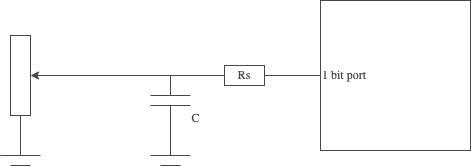
Fig. 1 QADC Rheostat Circuit#
The rheostat reader offers excellent linearity however it suffers from full scale setting accuracy if the passive components have large tolerances. This may result, for example with 20% tolerances, in full scale being read at 80% (and beyond) of the travel or only 80% being registered at the end of the travel. See the effect of passive components section for more details.
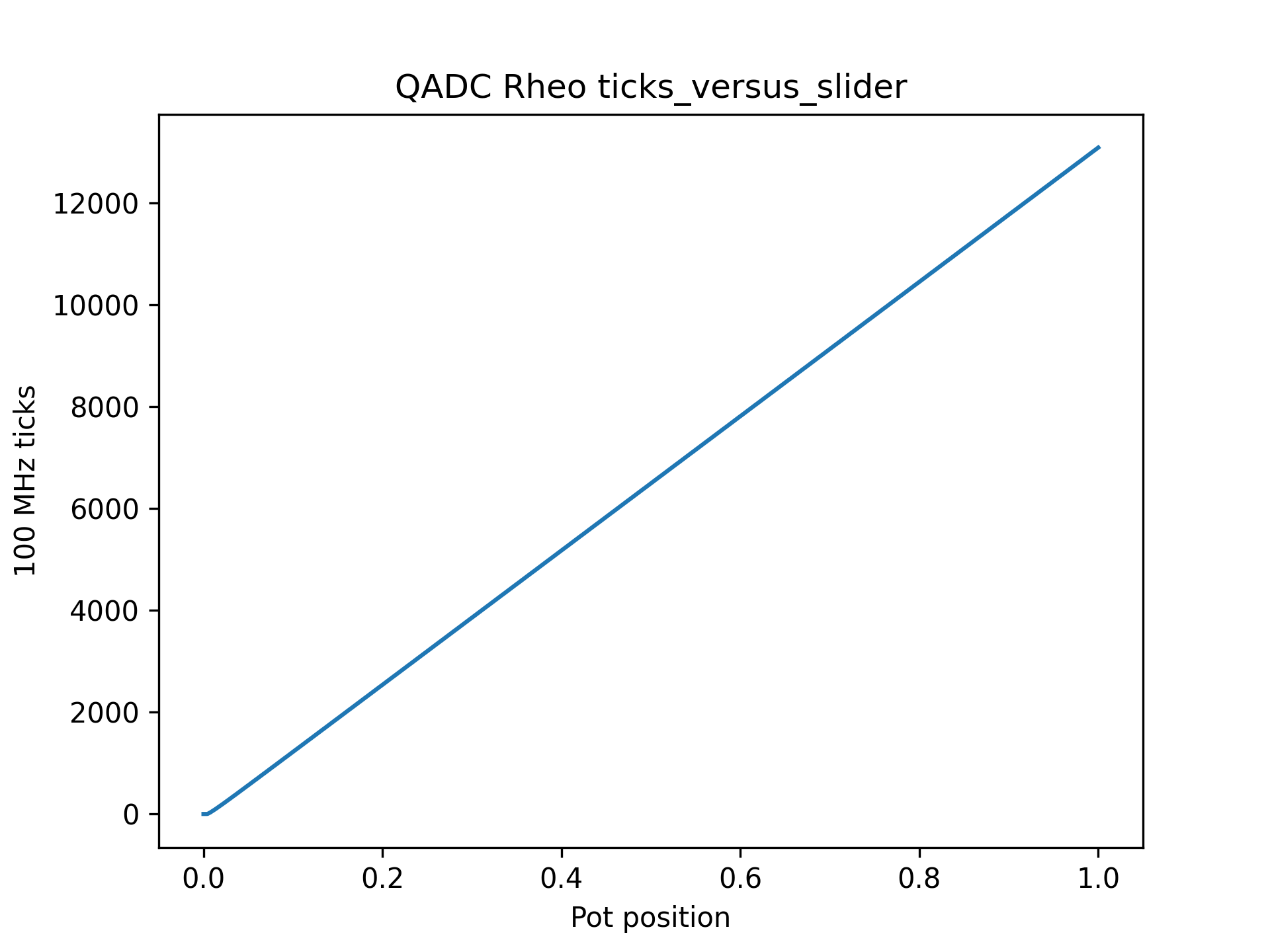
Fig. 2 QADC Rheostat Timer Ticks vs Position#
Note
If the QADC input pin is left disconnected you will see a full scale output.
Potential Reader#
The potential reader uses all three terminals of a potentiometer where the track end terminals are connected between ground and Vddio. Depending on the initial reading of the IO pin, the QADC either charges the capacitor to Vddio or discharges it ground and then times the transition through the threshold point to the potential set by the potentiometer, via the equivalent resistance of the potentiometer. The equivalent resistance of the potentiometer is the parallel of the upper and lower sections between the wiper and the end terminals.
Due to the reasonably complex calculation required to determine the estimated position from the transition time, which includes several precision multiplies, divides and a logarithm, a look up table (LUT) is pre-calculated at initialisation to make the conversion step more CPU efficient.
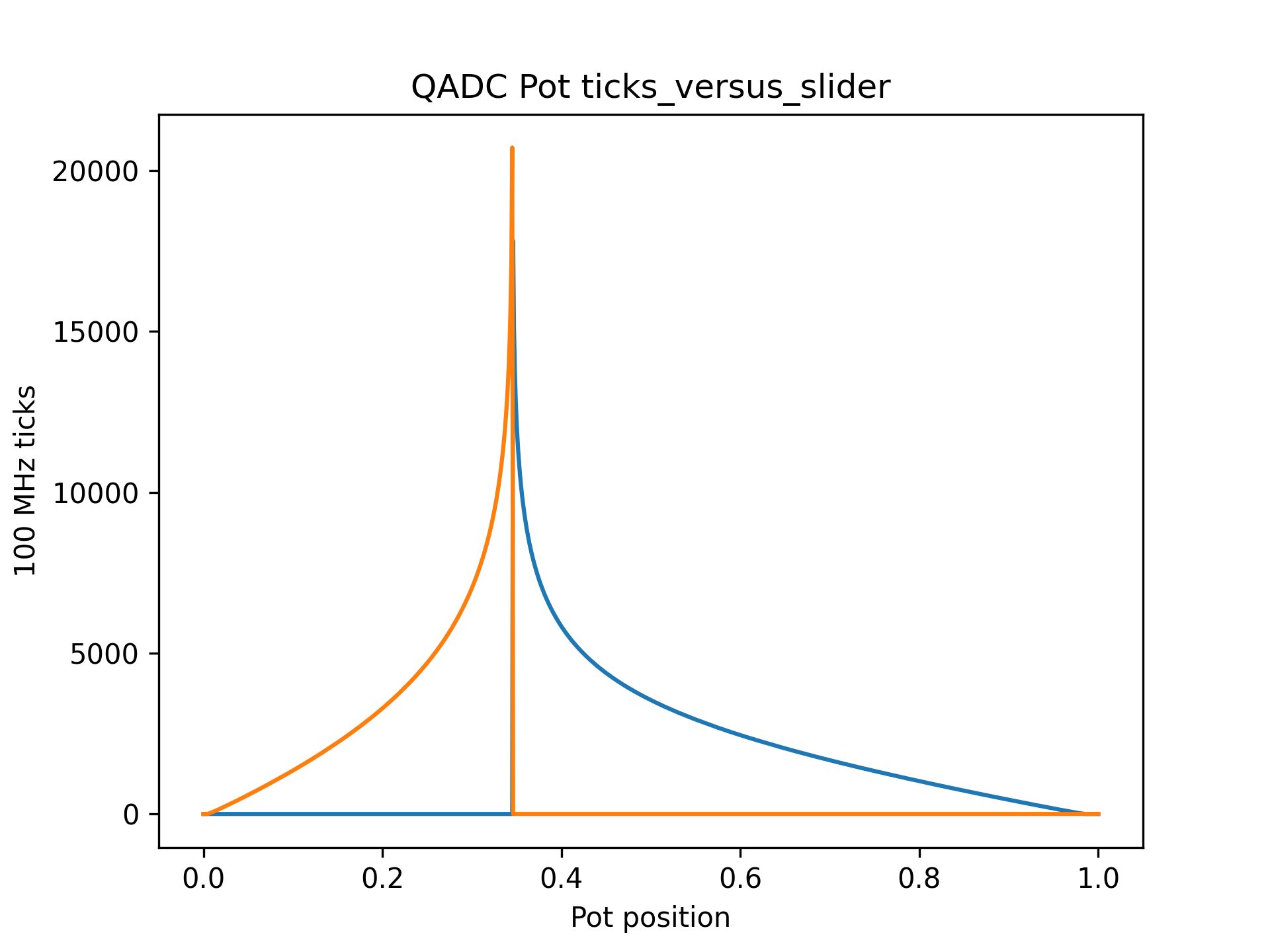
Fig. 3 QADC Potentiometer Timer Ticks vs Position#
Fig. 4 QADC Potentiometer Equivalent Resistance vs Position for 25 kOhm Component#
The scheme works as follows:
Read the current port value to see if voltage of the potentiometer is above or below threshold.
Set the inverse port value and wait to charge capacitor fully to the opposite supply rail.
Set the port to high impedance and take a timestamp.
Take a timestamp when voltage crosses threshold.
Use the lookup table to calculate the start voltage.
Post process value to reduce noise and improve linearity.
The rheostat reader currently supports arrays of any port width with the proviso that all ports are the same width.
The potential reader offers good performance and is less susceptible to component tolerances due to the mathematics of using a parallel resistor network and the logarithm used. It will always achieve zero and full scale however if tolerances are too large then it may show worse non-linearity than the rheostat reader and, in particular, around the 35% setting point which corresponds the threshold voltage of the IO. It does however always remain monotonic in operation. See the effect of passive components section for more details.
A small amount of noise is present when taking readings close to the threshold point. A moving average filter is typically used and so these non-linearities are reduced in practice and more than eight bits of resolution can easily be achieved.
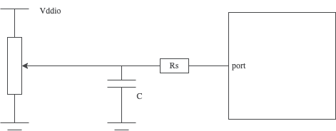
Fig. 5 QADC Potentiometer Circuit#
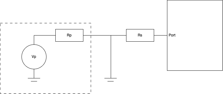
Fig. 6 QADC Potentiometer Equivalent Circuit#
Note
If the QADC input pin is left disconnected you will likely see a value of 35 % of full scale for the 1b port version and a value of close to zero for the wide port version.
Post Processing#
Both QADC schemes benefit from post processing of the raw measured transition time to improve performance.

Fig. 7 QADC Post Processing Steps#
The included post processing steps are as follows:
Moving Average Filter#
The moving average filter (sometimes know as a Boxcar FIR) helps filter out noise from the raw signal. It uses the conversion of history and takes the average value of the conversion and effectively low-pass filters the signal. One filter is provided per channel and the depth of the filter is configurable. A typical depth of 32 has been found to provide a good performance. Due to the low pass effect very long filters will reduce the response time of the QADC.
Scaling#
Scaling typically means reducing the raw resolution of the ADC from 12 - 13 bits and quantising it to a typical bit resolution such at 8, 9 or 10 bits. This provides a signal which has a know range, for example, 0 - 511 for the 9 bit case. This step also offers the possibility of calibration where the tolerance of the passive components may affect the estimated position of the input.
Hysteresis#
Even after filtering it may still be possible to see some small noise signal depending on configuration. This may also be exaggerated due to the natural quantisation to a digital value by the QADC, particularly if the setting is close to a transition point. By adding a small hysteresis (say a value of one or two) additional stability can be achieved at the cost of a very small dead zone at the last position. This may desirable if the QADC output is controlling a parameter that may be noticeable if it hunts between one or more positions. The hysteresis is configurable and may be removed completely if needed by setting to 0.
Comparing the Effect of Passive Component Tolerance on Both Schemes#
Both schemes offered will work very well when the overall passive component tolerances are good (e.g. 5%). However typical variable resistors/potentiometers are designed to produce good relative resistances rather than absolute resistances and often the end-to-end resistance tolerance can be as high as 20%. The QADC relies more on absolute resistances, particularly the rheostat approach.
When passive component tolerances are poor we see differing effects on the real-life transfer curves of actual position versus estimated position depending on the scheme used.
For the Rheostat approach we see the good linearity and zero scale performance is always retained however full scale is directly affected. For example, if the resistor tolerance is 20% too low then the time constant will be smaller than expected and the maximum setting that can be achieved is 80% even at full travel (orange curve). This can be seen in the rheostat transfer curve. If the resistor tolerance is 20% too high then full scale will be achieved at 80% travel and the last 20% of travel will give the same reading of full scale (green curve).
The small step close to zero is caused by the QADC not being able to charge the capacitor past the threshold voltage at low setting due to the required series resistor.
If a manufacturing test is an option to calibrate the component values then this is likely the best approach to adopt.
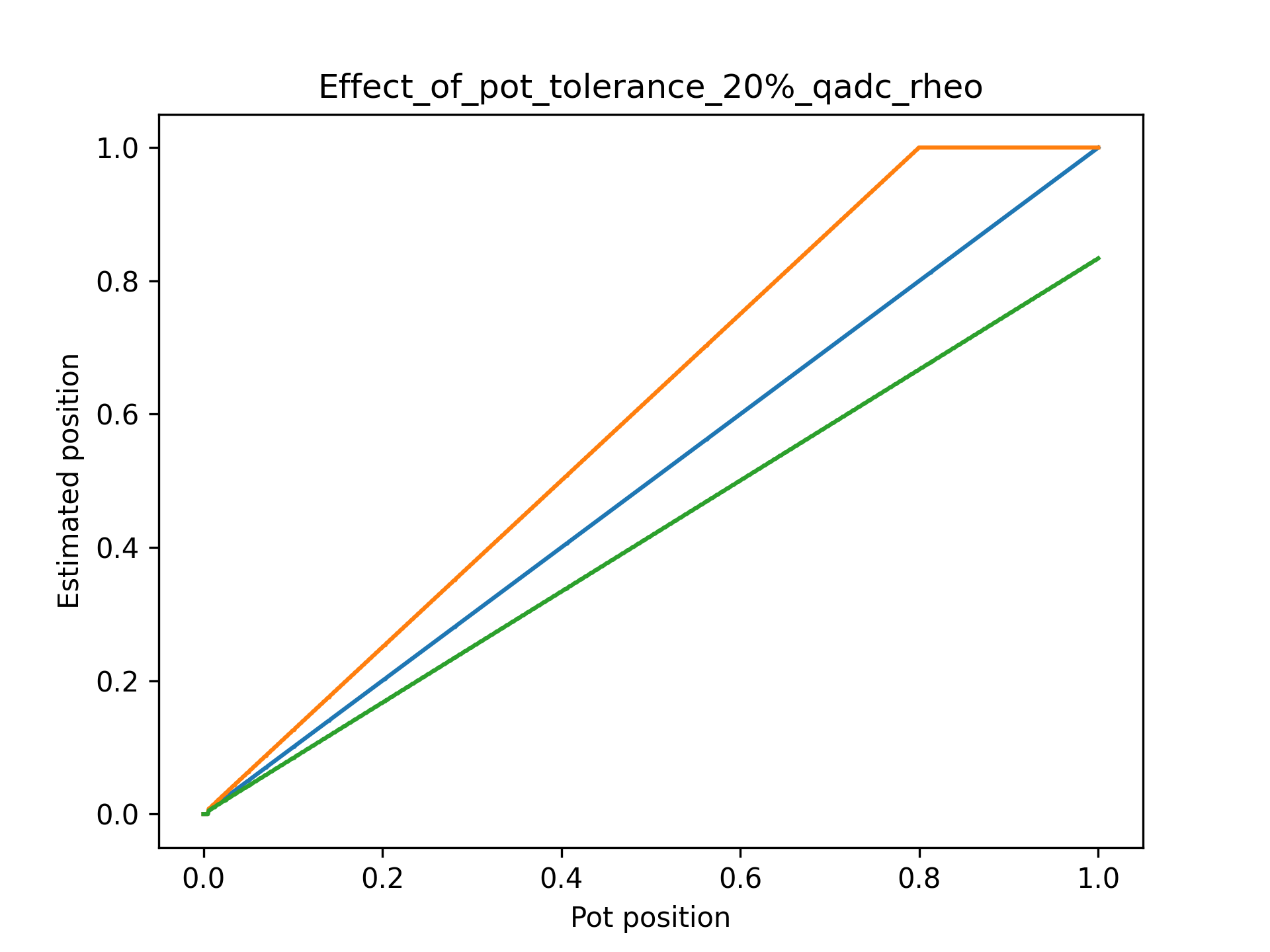
Fig. 8 QADC Rheostat Effect of 20% Tolerance on Transfer Curve#
The Potentiometer approach is more tolerant to the overall end to end resistance since it’s operation also relies on the starting potential as well as the equivalent series resistance at any given setting, which itself is a function of the end-to-end track resistance. Even when tolerance is 20% out the end positions will always achieve zero and full scale however linearity is slightly degraded and a small flat spot or inflection point may be seen at around 1/3 of the travel.
The curve will always remain monotonic increasing however the effect of noise (present in all ADCs) and the use of post processing (filtering and hysteresis) reduces the real life affect to a couple of percent of the travel, to a point where it may be unnoticeable.
Where the potentiometer end to end resistance is higher than set in the model, flat spot effect will be seen due to a higher than expected RC constant when the potentiometer is near to the GPIO input threshold voltage. Where the potentiometer end to end resistance is lower than set in the model, the inflection effect will be see due to the RC time constant being shorter than expected. This can be seen in the potentiometer transfer curve.
The small steps in the transfer curve close to zero and full scale settings are caused by the QADC not being able to charge the capacitor past the threshold voltage due to the potential divider effect of the series resistor and the potentiometer equivalent series resistance. Increasing the potentiometer value and decreasing the series resistor can reduce this effect.
Note
Overall, it is recommended to use the Potentiometer approach in cases where the potentiometer tolerance is between 10% and 20% and including a manufacturing calibration step is not practical.
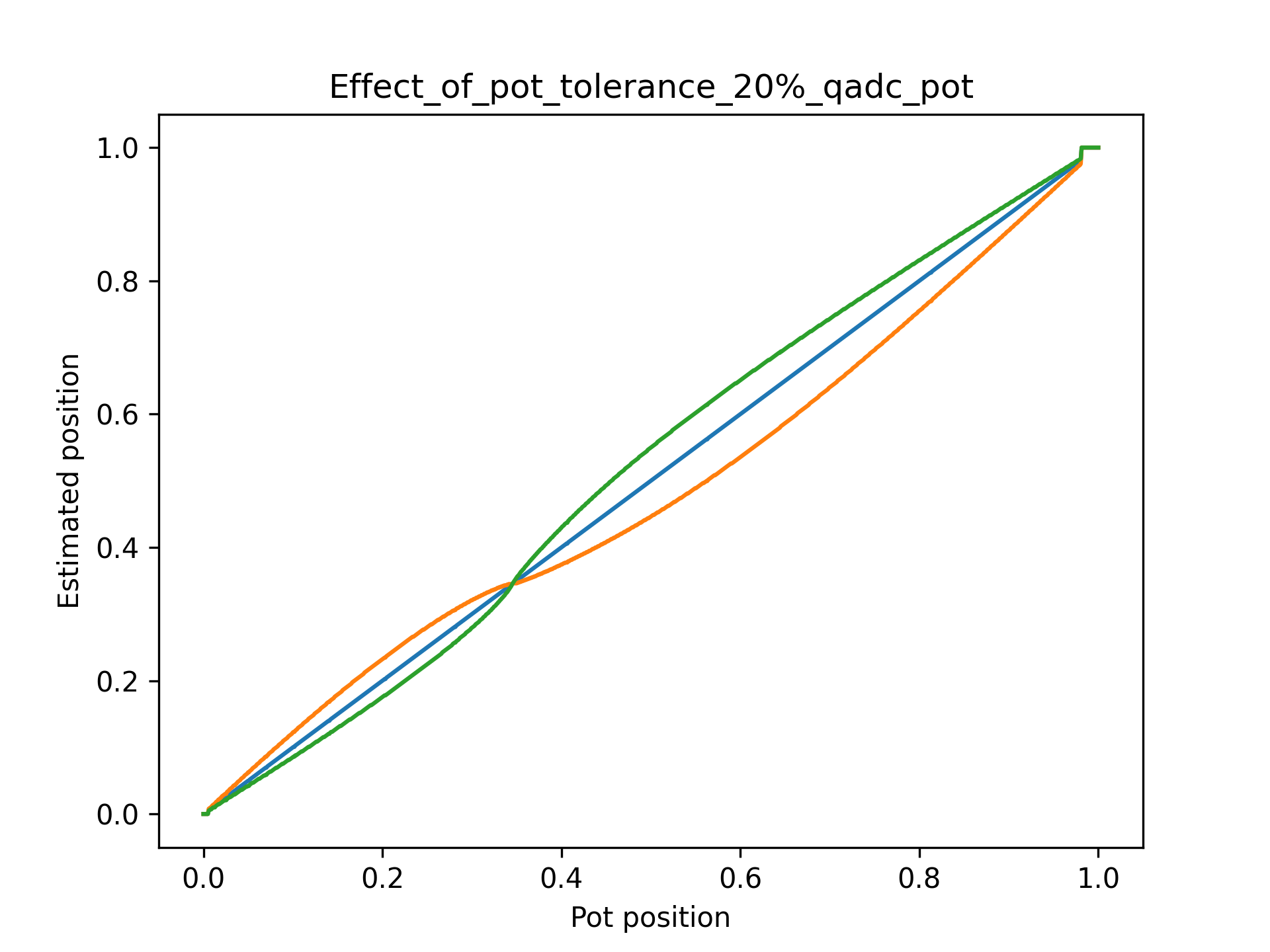
Fig. 9 QADC Potentiometer Effect of 20% Tolerance on Transfer Curve#
This theoretical behavior has been verified as shown in the Hardware Characterisation section of this document.
Passive Component Selection#
There are three components to consider when building one channel of QADC.
The variable resistor should be typically in the order of 20 - 50 kOhms. A lower value such as 10 kOhms may be used but it will either reduce the accuracy of the QADC slightly due to the increasing effect of the (required) series resistor and a reduced count or require the inclusion a larger capacitor to compensate which will increase power consumption due to greater charge/discharge amounts. The practical effect of this will also to be to increase the step sizes seen at the end positions of the transfer curves.
Choosing a value significantly of 100 kOhms or above may also decrease performance due to PCB parasitics or IO input leakage affecting the accuracy.
The capacitor value should by typically around 2 - 5 nF with the same trade-offs being seen as that of the variable resistor. A larger value is acceptable but it will increase the conversion time. A smaller value will increase noise and the effects of PCB stray capacitance may start to emerge. A 5 % tolerance C0G or similar capacitor is recommended although any type with good voltage vs. capacitance characteristics and 5 % tolerance is acceptable. Typical X7R decoupling capacitors are not ideal due to their negative voltage coefficient of capacitance which means the capacitance varies based on voltage.
The series resistor value is a compromise. Ideally it would set to a low value to reduce the small step effects in the transfer curve however this increases the current draw on the IO pin when the slider is close to end settings, which is undesirable and may cause noise. Typically a value of 1 % of the variable resistor value maximum is applicable with a minimum being around 330 ohms to limit the inrush current to the capacitor. Smaller values may cause unwanted EMI when the IO pin charges the capacitor although the IO drive settings are set to the minimum of 2 mA in QADC to minimise this effect.
Typical values recommended are:
Capacitor value |
Potentiometer value |
Series resistor value |
Conversion cycle time |
|---|---|---|---|
2200 pF 5% |
47 - 100 kOhms, 20 % or better (10 % ideally) |
470 Ohms, 5 % or better |
1 millisecond (= 100,000 10 MHz timer ticks) |
QADC Tuning#
Once the passive components have been selected then you can configure your QADC. Both schemes share a common configuration of type qadc_config_t as shown in the API section.
Note
It is highly recommended to prototype the values and test the configuration before deployment. There are natural sources of error in any analog scheme and these should be evaluated by the user.
The qadc_config_t configuration can be initialised (using C in this example rather than XC) as follows:
    const qadc_config_t adc_config = {  .capacitor_pf = 2000,
                                        .potentiometer_ohms = 47000,
                                        .resistor_series_ohms = 470,
                                        .v_rail = 3.3,
                                        .v_thresh = 1.15,
                                        .auto_scale = 0,
                                        .convert_interval_ticks = 1 * XS1_TIMER_KHZ};
The passive component selection should be directly inputted into the structure and nominal values of 3.3 and 1.15 used for the IO voltage and threshold voltage. If the IO voltage is known to be say 5 % lower than 3.3 then please scale both values accordingly (e.g. 3.135 and 1.0925).
The final three settings require some thought and are described below.
How to set auto_scale#
Autoscale works by measuring the time taken to reach the conversion result. If it takes longer than expected (full scale for rheostat or 35% setting for potentiometer) then it trims the max value so that the reading can be made more accurate during the following runtime of the QADC (until reset).
It can help cases where the RC constant is larger than expected however it is not possible to detect where the RC constant is smaller than expected because this is indistiguishable from a normal lower setting.
It may be helpful to use this setting if you choose to set the RC settings in the code a little lower than nominal to achieve better range. However it must be noted that the first full transition of QADC must complete before the new max is learnt and so will behave slightly differently to subsequent transitions.
Set this value to 0 by default.
How to set convert_interval_ticks#
This parameter is only relevant to continuous mode where a task cycles through the QADCs. It sets the total period per conversion which includes charging the capacitor, measuring the discharge periods and an idle time at the end to allow the capacitor to reach it’s natural voltage governed by the external passives.
The QADC will check the set values and automatically assert if the following condition is not met:
convert_interval_ticks > (max_charge_period_ticks + max_disch_ticks * 2)
The max_charge_period_ticks is nominally 5 times the RC constant and max_disch_ticks is calculated by the code as the maximum time to reach the threshold voltage when the IO goes high impedance. This is doubled to allow for some idle time and provides a safe setting. A typical setting will be in the region of one millisecond, depending on passive value selection.
In single shot mode the setting is ignored because the API takes the correct amount of time to account for all required steps and the function returns when the result is ready.
QADC Usage#
There are three main modes of operation for the QADC.
Continuous Modes#
If many channels are needed and continuous updates are required then it is convenient to run a task which performs background continuous conversion and associated filtering. This requires a dedicated hardware thread.
The values may then be read by the application either:
Over a channel (application on same or different tile from the QADC) or
By shared memory (same tile only) using the adc_xxx_state.results member which is a pointer to an array of
unit16_tresult values.
The examples included in the QADC repo under /examples show both continuous modes in use.
Single Shot Mode#
A single shot API is also available which allows a single conversion to be performed by calling a function. Note that the function call is blocking and will return only when the conversion is complete. This will typically take a few hundred microseconds for the recommended passive component selection.
When infrequent conversions are made using single shot mode it is recommended to reduce the depth of the moving average filter down to the actual number conversions performed for each desired QADC value.
The examples included in the QADC repo under /examples show the single shot mode in use.
QADC API#
Common API#
Common items for both types of QADC are shown here.
Note
Depending on whether QADC is called from an XC program with a par{} or from C with PAR_JOBS() extra hardware setup may be needed. If using PAR_JOBS() please call qadc_pre_init_c() before QADC initialisation.
See the QADC Tuning section for more details on setting these values.
-
struct qadc_config_t#
Configuration structure for initialising the QADC. This contains the passive component definition, voltages, conversion speed ( adc_xxx_task() only ) and mode.
Public Members
-
unsigned capacitor_pf#
Capacitor size in picofarads. Should include the stray capacitance of the PCB.
-
unsigned potentiometer_ohms#
Potentiometer value in ohms - nominal maximum value end to end.
-
unsigned resistor_series_ohms#
Series resistor size in ohms.
-
float v_rail#
Voltage of the IO rail used by the QADC port as a float.
-
float v_thresh#
Voltage of the input threshold. This is nominally 1.15 volts for a 3.3 volt rail.
-
char auto_scale#
Boolean setting which allows the largest time seen by the conversion to be trimmed if it exceeds the expected value. The new end point will be kept until the task is re-started. It can account for cases where the RC delay constant is much larger than expected. Note no scheme is available for detecting the case where the RC constant is shorter than expected.
-
unsigned convert_interval_ticks#
The full conversion cycle time per channel (adc_xxx_task() only). The task will assert at initialisation if this is too short. This setting is ignored in single-shot mode.
-
unsigned capacitor_pf#
-
typedef uint16_t qadc_q3_13_fixed_t#
Fixed point type used internally by QADC.
-
void qadc_pre_init_c(port p_adc[], size_t num_adc)#
Perform xcore resource setup if QADC is to be used from C with lib_xcore PAR_JOBS(). Because QADC is written in XC it expects ports to be enabled and an XC timer to be available. This pre-init function meets those needs if using from a lib_xcore based project
- Parameters:
p_adc – An array of ports used for conversion.
num_adc – The number of QADC channels used
-
QADC_CMD_READ#
Read an ADC channel, arg: channel number in LSB. Please OR the cmd with the operand.
-
QADC_CMD_CAL_MODE_START#
Start calibration mode. Move the potentiometer end to end to determine limits.
-
QADC_CMD_CAL_MODE_FINISH#
Stop calibration mode and use new observed limits.
-
QADC_CMD_POT_GET_DIR#
Read the conversion direction. Potentiometer QADC only. (1 = High to low, 0 = Low to high) of an ADC channel, arg: channel number in LSB. Please OR the cmd with the operand.
-
QADC_CMD_STOP_CONV#
Temporarily stop conversion.
-
QADC_CMD_START_CONV#
Restart conversion.
-
QADC_CMD_EXIT#
Exit the qadc_pot_task().
-
QADC_CMD_MASK#
Mask word used for building commands.
-
QADC_Q_3_13_SHIFT#
The shift value needed to work with qadc_q3_13_fixed_t.
QADC Rheostat API#
Specific items for the Rheostat QADC are shown here.
-
struct qadc_rheo_state_t#
Internal state for each QADC instance. These should not be accessed directly and instead be initialised by a call to adc_rheo_init().
-
void qadc_rheo_init(port p_adc[], size_t num_adc, size_t adc_steps, size_t filter_depth, unsigned result_hysteresis, uint16_t *state_buffer, qadc_config_t adc_config, REFERENCE_PARAM(qadc_rheo_state_t, adc_rheo_state))#
Initialise a QADC rheostate reader instance and initialise the qadc_rheo_state structure. This generates the look up table, initialises the state and sets up the ports used by the QADC. Must be called before either qadc_rheo_single() or qadc_rheo_task().
IF CALLING FROM C WITH lib_xcore’s PAR_JOBS() TO START THE THREADS, PLEASE CALL qadc_c_pre_init() FIRST.
- Parameters:
p_adc – An array of 1 bit ports used for conversion.
num_adc – The number of 1 bit ports (QADC channels) used.
adc_steps – The number of discrete conversion possible values. Also sets the output result full scale value to lut_size - 1.
filter_depth – The size of the moving average filter used to average each conversion result.
state_buffer – pointer to the state buffer used of type uint16_t. Please use the ADC_POT_STATE_SIZE macro to size the declaration of the state buffer.
adc_config – A struct of type qadc_config_t containing the parameters of the QADC external components and conversion rate / mode. This must be initialised before passing to qadc_rheo_init().
adc_rheo_state – Reference to the qadc_rheo_state_t struct which contains internal state for the QADC. This does not need to be initialised before hand since this function does that.
-
uint16_t qadc_rheo_single(port p_adc[], unsigned adc_idx, REFERENCE_PARAM(qadc_rheo_state_t, adc_rheo_state))#
Perform a single ADC conversion on a specific channel. In this mode the QADC does not require a dedicated task (hardware thread) to perform conversion. Note that this is a blocking call which will return only when the conversion is complete. Typically it may take a few hundred microseconds (depending on the RC constants chosen) but it’s execution time is variable. It will take longest when the rheostate is set to maximum and shortest at zero. Use this API when infrequent readings are needed and the callee can accept a blocking call. qadc_rheo_init() must be called before this function.
- Parameters:
p_adc – An array of 1 bit ports used for conversion.
adc_idx – The QADC channel to read.
adc_rheo_state – Reference to the adc_rheo_state_t struct which contains internal state for the QADC.
-
void qadc_rheo_task(NULLABLE_RESOURCE(chanend, c_adc), port p_adc[], REFERENCE_PARAM(qadc_rheo_state_t, adc_rheo_state))#
-
QADC_RHEO_STATE_SIZE(num_adc, filter_depth)#
QADC Potentiometer API#
Specific items for the Potentiometer QADC are shown here.
-
struct qadc_pot_state_t#
Internal state for each QADC instance. These should not be accessed directly and instead be initialised by a call to adc_pot_init().
-
void qadc_pot_init(port p_adc[], size_t num_adc, size_t lut_size, size_t filter_depth, unsigned result_hysteresis, uint16_t *state_buffer, qadc_config_t adc_config, REFERENCE_PARAM(qadc_pot_state_t, adc_pot_state))#
Initialise a QADC potentiometer reader instance and initialise the qadc_pot_state structure. This generates the look up table, initialises the state and sets up the ports used by the QADC. Must be called before either qadc_pot_single() or qadc_pot_task().
IF CALLING FROM C WITH lib_xcore’s PAR_JOBS() TO START THE THREADS, PLEASE CALL qadc_c_pre_init() FIRST.
- Parameters:
p_adc – An array of ports used for conversion. Must all be of same time (eg. 1b or 4b ports)
num_adc – The number of ADC channels needed. Where ports other than 1b ports are used, the lower pins on the port are used first. Eg. bottom 2 pins of a 4b port are used if num_adc = 2. The other pins on the port are reserved.
lut_size – The size of the look up table. Also sets the output result full scale value to lut_size - 1.
filter_depth – The size of the moving average filter used to average each conversion result.
state_buffer – pointer to the state buffer used of type uint16_t. Please use the ADC_POT_STATE_SIZE macro to size the declaration of this state buffer.
adc_config – A struct of type qadc_config_t containing the parameters of the QADC external components and conversion rate / mode. This must be initialised before passing to qadc_pot_init().
adc_pot_state – Reference to the qadc_pot_state_t struct which contains internal state for the QADC. This does not need to be initialised before hand since this function does that.
-
uint16_t qadc_pot_single(port p_adc[], unsigned adc_idx, REFERENCE_PARAM(qadc_pot_state_t, qadc_pot_state))#
Perform a single ADC conversion on a specific channel. In this mode the QADC does not require a dedicated task (hardware thread) to perform conversion. Note that this is a blocking call which will return only when the conversion is complete. Typically it may take a few hundred microseconds (depending on the RC constants chosen) but it’s execution time is variable. It will take longest when the potentiometer is set to roughly 1/3 and shortest as the end positions. Use this API when infrequent readings are needed and the callee can accept a blocking call. qadc_pot_init() must be called before this function.
- Parameters:
p_adc – An array of ports used for conversion.
adc_idx – The QADC channel to read.
qadc_pot_state – Reference to the qadc_pot_state_t struct which contains internal state for the QADC.
-
void qadc_pot_task(NULLABLE_RESOURCE(chanend, c_adc), port p_adc[], REFERENCE_PARAM(qadc_pot_state_t, adc_pot_state))#
-
QADC_POT_STATE_SIZE(num_adc, lut_size, filter_depth)#
Macro for sizing the state array used by QADC. Please declare a state array (linear array) of uint16_t sized by this macro for passing to qadc_pot_init().
num_adc - The number of channels.
lut_size - The size of the look up table. Also sets the maximum conversion value to (lut_size - 1). One LUT is used for all channels.
filter_depth - The depth of the moving average filter (1 to n). Has a large impact on the memory requirements because each channel requires it’s own filter.
Building and running the examples#
The examples are designed to run on the XK-EVK-XU316 (XCORE-AI-EXPLORER) kit although any xcore.ai hardware will work (please adjust the QADC ports accordingly).
Ensure a correctly configured installation of the XMOS tools and open an XTC command shell. Please check that the XMOS tools are correctly sourced by running the following command:
$ xcc
xcc: no input files
Note
Instructions for installing and configuring the XMOS tools appear on the XMOS web site.
Clone the lib_qadc repository:
git clone git@github.com:xmos/lib_qadc.git
cd lib_qadc
Next ensure you have adjusted the relevant paramters for your design:
#define NUM_ADC             2
#define LUT_SIZE            1024
#define FILTER_DEPTH        16
#define HYSTERESIS          1

// Select your port as required. Either 1b or wide ports may be used.
// on tile[1]: port p_adc[] = {XS1_PORT_1M, XS1_PORT_1O}; // Sets which pins are to be used (channels 0..n) X1D36/38
            const unsigned capacitor_pf = 8800;        // Set the capacitor value here
            const unsigned potentiometer_ohms = 10000; // Set the potenitiometer nominal maximum value (end to end)
            const unsigned resistor_series_ohms = 220; // Set the series resistor value here

            const float v_rail = 3.3;
            const float v_thresh = 1.15;
            const char auto_scale = 0;

            const unsigned convert_interval_ticks = (1 * XS1_TIMER_KHZ); // 1 millisecond
Run the following commands in the lib_sw_pll/examples directory to build the firmware:
cmake -B build -G "Unix Makefiles"
xmake -j -C build
To run the example firmware, first connect the required passive circuitry to the QADC input pins and the run one of the following examples as appropriate:
xrun --xscope pot_reader/bin/SINGLE/qadc_pot_example_SINGLE.xe
xrun --xscope pot_reader/bin/CONTINUOUS_CHAN/qadc_pot_example_CONTINUOUS_CHAN.xe
xrun --xscope pot_reader/bin/CONTINUOUS_MEM/qadc_pot_example_CONTINUOUS_MEM.xe
xrun --xscope rheo_reader/SINGLE/bin/qadc_rheo_example_SINGLE.xe
xrun --xscope rheo_reader/CONTINUOUS_CHAN/bin/qadc_rheo_example_CONTINUOUS_CHAN.xe
xrun --xscope rheo_reader/CONTINUOUS_MEM/bin/qadc_rheo_example_CONTINUOUS_MEM.xe
In each case the converted QADC values will be periodically printed to the console, for example:
Running QADC in continuous mode using dedicated task!
Read channel ch 0: 558, ch 1: 328,
Read channel ch 0: 558, ch 1: 330,
Read channel ch 0: 558, ch 1: 342,
Read channel ch 0: 536, ch 1: 364,
Read channel ch 0: 488, ch 1: 428,
Read channel ch 0: 420, ch 1: 490,
Read channel ch 0: 373, ch 1: 516,
Read channel ch 0: 337, ch 1: 544,
Read channel ch 0: 305, ch 1: 570,
Read channel ch 0: 277, ch 1: 592,
Read channel ch 0: 251, ch 1: 610,
Read channel ch 0: 219, ch 1: 634,
...
Hardware Characterisation of QADC Potentiometer Transfer Curve#
A bench characterisation of the QADC potentiometer was conducted to verify the model. A 10 bit ADC was connected to the potentiometer and the voltage reading (reference voltage was logged). The QADC was configured to 10 bits then enabled and the estimated potentiometer setting was logged against the reference.
In this case, less than ideal settings of 10 k for the potentiometer was used (causing a noticeable step at the end of the transfer curve) however the effect of 0 %, 20 % and -20 % deviation in the specified RC constant against the values used can be seen.
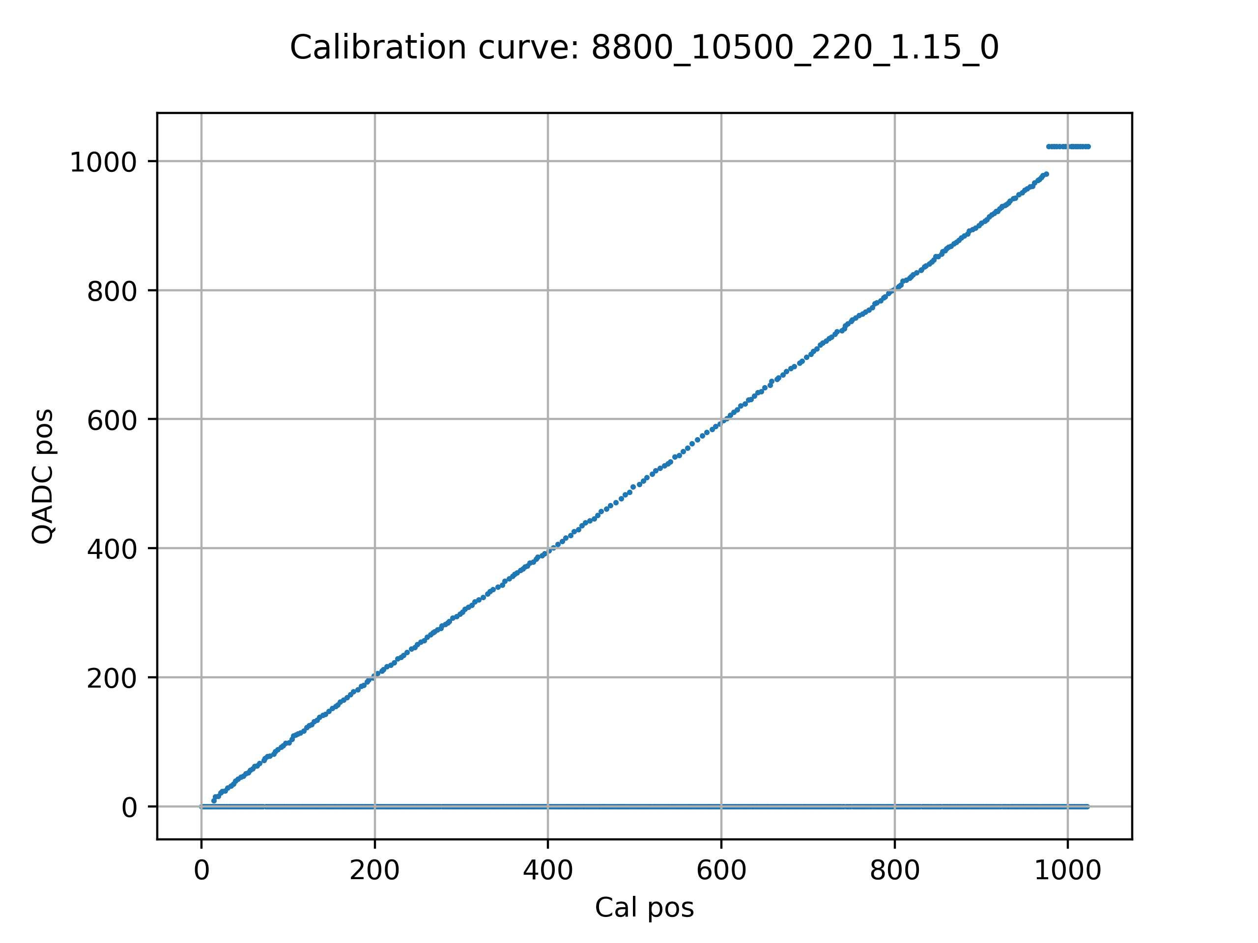
Fig. 10 QADC Potentiometer Transfer curve with 0 % Tolerance RC settings#
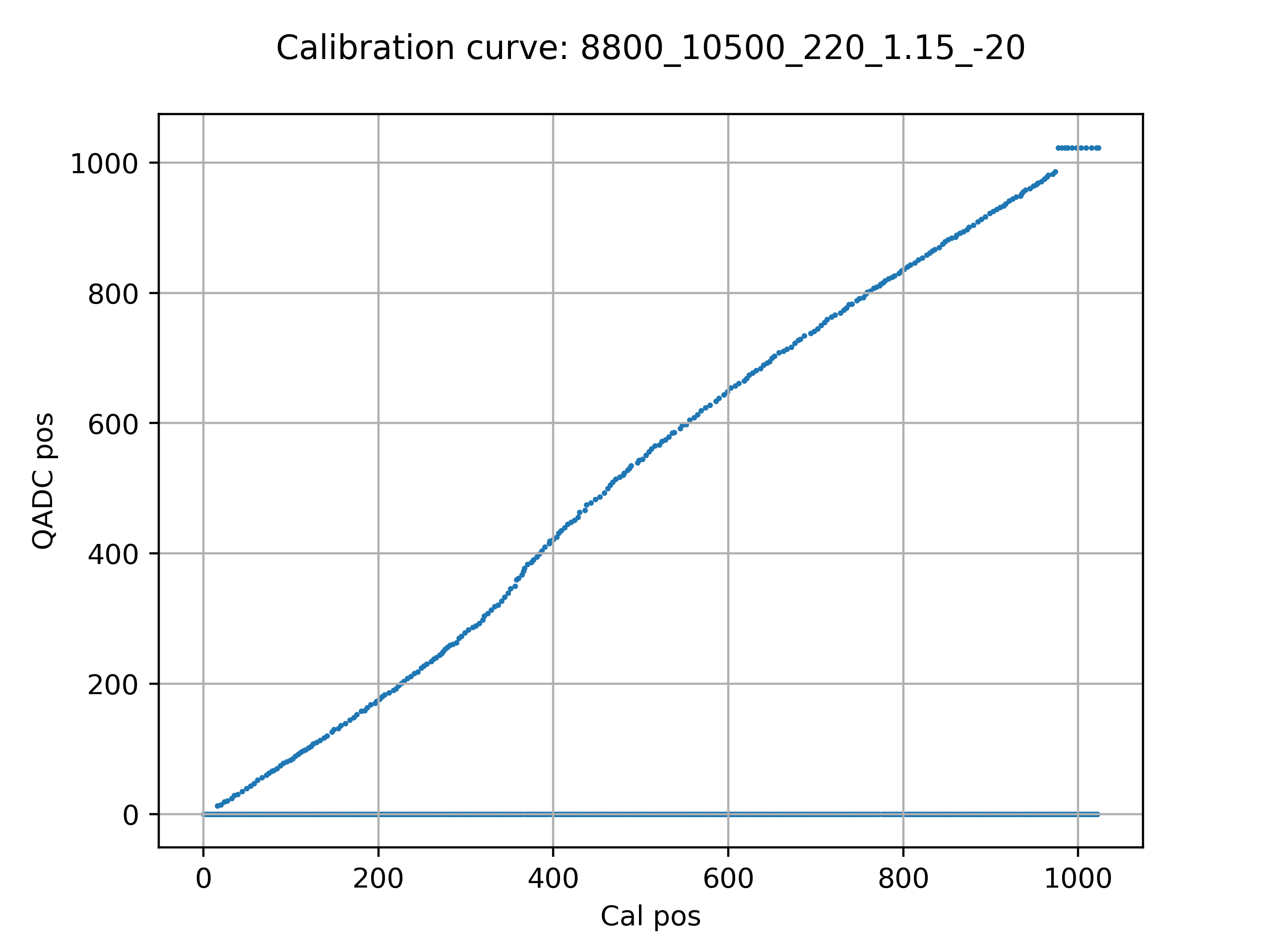
Fig. 11 QADC Potentiometer Transfer curve with -20 % Tolerance RC settings#
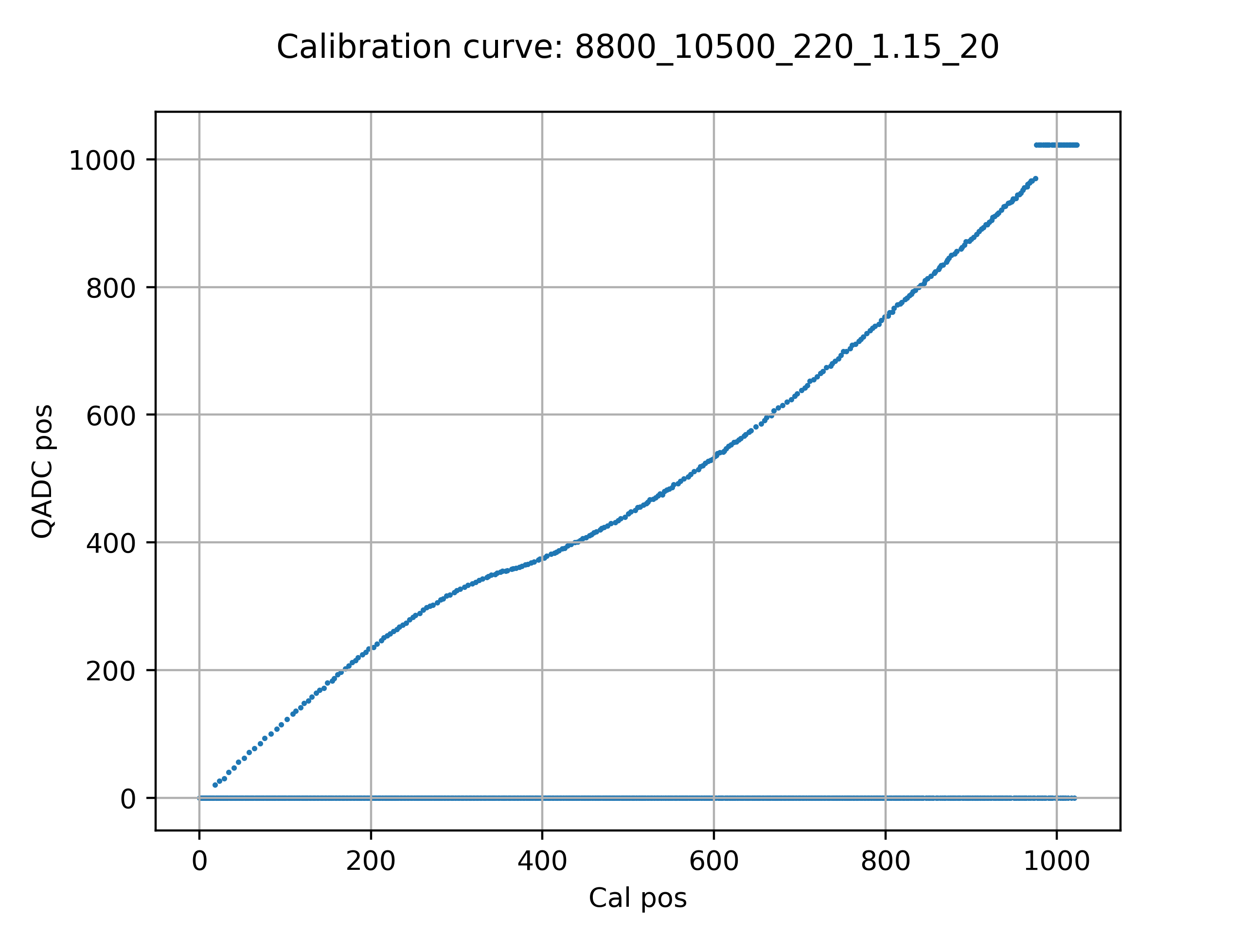
Fig. 12 QADC Potentiometer Transfer curve with +20 % Tolerance RC settings#
It can be seen that, although the linearity is affected by +- 20% tolerance, the transfer curve remains monotonic and the end positions can always be reached. It also confirms that the model closely matches the practical operation of the QADC.
The python model of the QADC may be found in the /design directory of the QADC repo and is used in the regression test to ensure the embedded version matches.