AN02015: Run-time DSP control in a USB Audio Application#
Introduction#
This application note is complementary to “AN02014: Integrating a Generated Audio DSP Pipeline into a USB Audio Application”. The goal is to show how to read and write the DSP configuration at run-time; building dynamic features into the application. The application associated with this note makes use of the buttons and LEDs on the XK-AUDIO-316-MC-AB to implement an active speaker application with volume control and bass boost. The DSP pipeline also computes the RMS power of the signal and displays this on the 4 LEDs to provide a simple VU meter.
Getting Started#
Requirements#
Before running this application note ensure the following applications are installed on your system:
XTC 15.3.0
CMake >= 3.21.0
Python 3.12
Graphviz, ensuring the dot executable available on your PATH.
The following hardware is required:
2 Micro-USB cables
An audio device with a 3.5 mm jack (e.g. speakers or headphones)
Running the example#
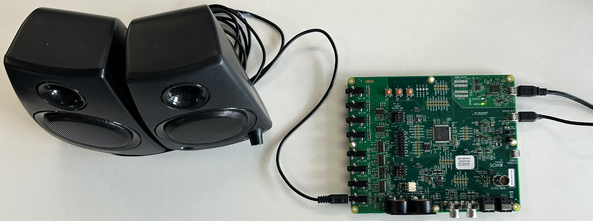
First, connect the XK-AUDIO-316-MC-AB to your computer with both the “DEBUG” and “USB DEVICE” Micro-USB ports as shown in Fig. 1.

Fig. 1 XK-AUDIO-316-MC-AB with both USB cables connected and a pair of speakers connect to OUT 1/2#
Once connected follow these steps:
Open a terminal and activate the XTC enviroment (see XTC getting started). Optionally, create a Python virtual environment and activate it.
Get the source code for this app note from https://www.xmos.com/application-notes/
Navigate to the root directory of this app note and install the Python requirements:
pip install -Ur requirements.txt
Start the Jupyter notebook from the
app_dsp_and_usbdirectory. Jupyter Notebook is an interactive Python editor which was installed via the pip command in the previous step.cd app_dsp_and_usb jupyter notebook
If this does not automatically open a browser window, then copy the URL from the output of
jupyterthat starts withhttp://127.0.0.1and navigate to it in your web browser.Open “dsp.ipynb” on the web interface by double-clicking on the file name.
Execute all the cells in the notebook by selecting “Run all cells” from the “Run” menu.
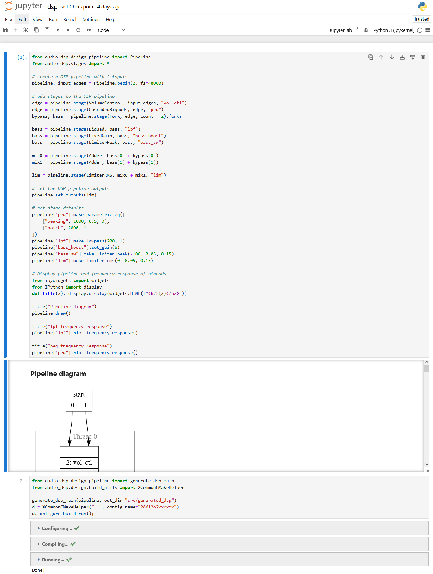
This final step will display a diagram that represents the provided simple DSP pipeline. It will then generate the xcore source code, build the application, and run it on the connected device. A screenshot of the notebook after successful completion is shown in Fig. 2. The device will appear on the connected computer as a stereo USB audio device named “XMOS xCORE.ai MC (UAC2.0)”, supporting recording and playback.
When audio is played to the USB device from the host PC, the output can be heard by connecting a speaker or headphones to the “OUT 1/2” jack on the XK-AUDIO-316-MC-AB. Button 0 will toggle bass boost; button 1 increases the volume; button 2 decreases the volume. The LEDs will show the signal power level, when no audio is playing all the LEDs will be off.
Caution
To get all 4 LEDs to illuminate the signal will have to be very loud! Take special care when connecting headphones to the XK-AUDIO-316-MC-AB.

Fig. 2 The notebook after running successfully#
Application Overview#
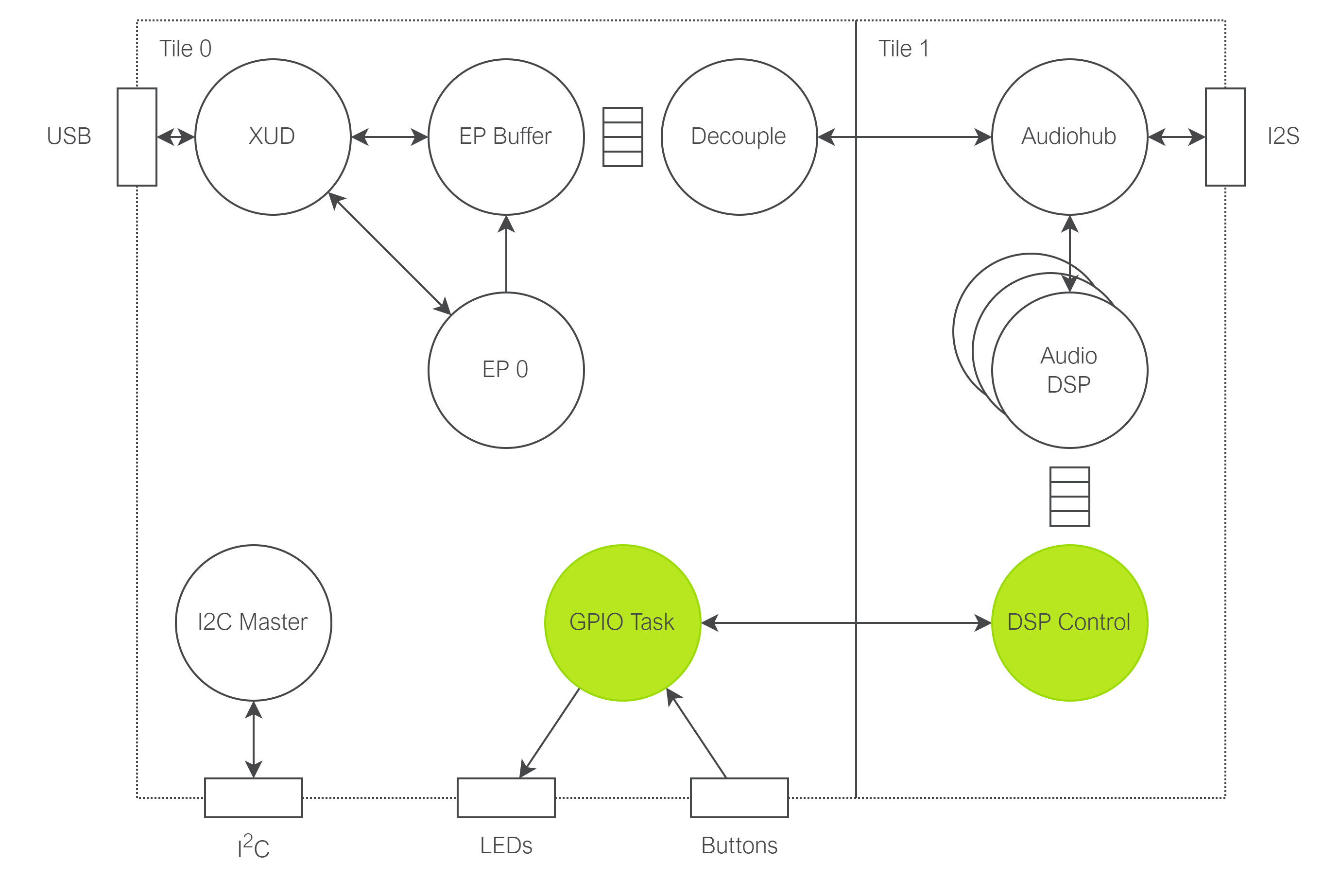
The application accompanying this note is largely the same as that in AN02014. It is an sw_usb_audio application with a DSP pipeline generated using the generation tools from lib_audio_dsp. The DSP pipeline and I2S both run on tile 1. On the XK-AUDIO-316-MC-AB the buttons and LEDs are connected to ports 4E and 4F respectively, both on tile 0. The run-time control guide associated with lib_audio_dsp describes the DSP control interface that can be used to modify the DSP configuration. The main constraint is that this must be done from the same tile as the DSP threads. Accessing the ports for the buttons and LEDs must be done the tile that they are connected to, tile 0. Hence, this application required an additional 2 threads compared to the base application from AN02014. These threads are show in Fig. 3.

Fig. 3 System thread diagram#
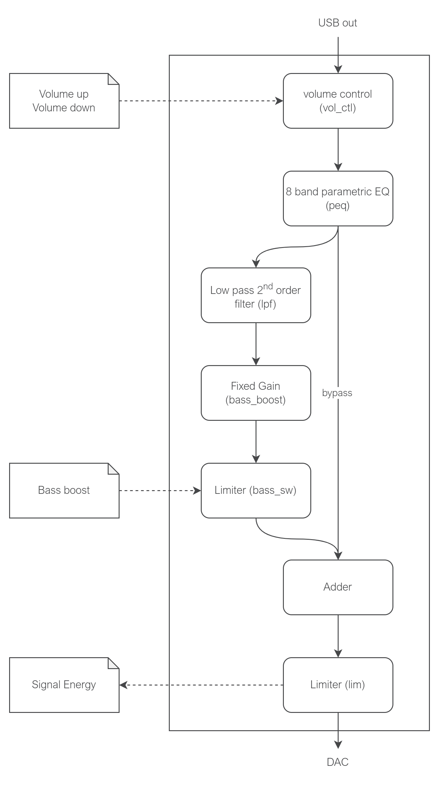
The DSP pipeline for this application is shown in Fig. 4. It contains the following stages, all of which are stereo:
Volume control (vol_ctl): Adjust the volume of the input signal.
8 band parametric EQ (peq): Configurable PEQ to adjust for the listeners preference or to account for the speaker response.
Low pass filter (lpf), fixed gain (bass_boost) and limiter (bass_sw): This path takes the low frequencies and applies a boost to them. The fixed gain sets the magnitude of the boost. The output limiter reduces the level of the bass boost for large signals, avoiding overloading the loudspeaker at the output. This output limiter can be used to adjust the level of the bass boosted signal before it is summed with the bypass signal. Adjusting the limiter threshold can have the effect of enabling or disabling the bass boost effect. A low limiter threshold will mean the bass boost path is always held to a small signal level.
Adder: combines bass boost signal with bypass signal to create a signal with boosted bass and unmodified higher frequencies.
Limiter (lim): Compresses the output of the DSP pipeline to prevent clipping. The limiter computes an envelope of the signal which can be read out via its
envelopeparameter. This functionality will be used to determine which LEDs to light.

Fig. 4 DSP graph diagram, stage labels for use in control shown in brackets. Dashed arrows indicate which stages will be accessed for the user interface#
Creating the Control and GPIO Threads#
In this application, the two thread entry functions (see Fig. 3) are gpio_task, defined in
“gpio_task.c”, and dsp_control, defined in “app_dsp.c”. Both functions take a chanend as their only parameter which
is used to communicate between the two tiles. To spawn these threads the first step is to define the new channel in
user_main.h, and then to place the gpio function on tile 0, passing it one end of the channel. The other end of the
channel is passed to dsp_thread on tile 1. Below is an excerpt from “user_main.h”:
#define USER_MAIN_DECLARATIONS \
    interface i2c_master_if i2c[1];\
    chan c_gpio;

#define USER_MAIN_CORES on tile[0]: {\
                                        board_setup();\
                                        xk_audio_316_mc_ab_i2c_master(i2c);\
                                    }\
                        on tile[0]: gpio_task(c_gpio);\
                        on tile[1]: {\
                                        {\
                                            unsafe { i_i2c_client = i2c[0]; }\
                                            dsp_thread(c_gpio);\
                                        }\
                                    }
The GPIO Thread#
The GPIO thread, in “gpio_task.c” makes use of lib_xcore to implement some basic button logic. It also uses a hardware timer to trigger a periodic query of the current signal level to update the LEDs.
The DSP Control Thread#
Overview of control features#
The DSP control thread is spawned in parallel with adsp_auto_pipeline_main in the top level DSP function dsp_thread.
dsp_thread is defined in app_dsp.c and shown in the excerpt below. This structure ensures that the control thread and
the DSP thread will always be on the same tile.
void dsp_thread(chanend_t c_gpio) {
    // Initialise the DSP instance and launch the generated DSP main function
    // as well as the control thread
    m_dsp = adsp_auto_pipeline_init();
    PAR_JOBS(
        PJOB(adsp_auto_pipeline_main, (m_dsp)),
        PJOB(dsp_control, (c_gpio))
    );
}
The DSP control thread entry function dsp_control, defined in app_dsp.c, is shown below. This function implements a
simple channel based server protocol that interfaces with the GPIO thread on the other tile. This means that the thread
is idle until it receives a communication from the GPIO thread, then it reads from the channel to determine
what work is required. In this case the GPIO thread chooses from one of 4 operations:
BASS_BOOST_SW: Toggle the bass boost. The GPIO thread will request this when the bass boost button is pressed. When this request is received it triggers the DSP control thread to update the threshold in thebass_swlimiter.VOLUME_UP: Increase the volume. This will be called when the volume up button is pressed. On receiving this request the DSP control thread will read the current target volume from the DSP volume control stage. Then the new volume is calculated and written to the DSP stage.VOLUME_DOWN: Decrease the volume. This will be called when the volume down button is pressed. The logic for volume down is the same as volume up.GET_VU_LEVELS: The GPIO thread uses a hardware timer to call this periodically. On reception the DSP control thread will read the energy level from thelimlimiter and convert this into a port value for the LEDs. This LED port value is sent back over the channel to the GPIO thread.
void dsp_control(chanend_t c_gpio) {
    xassert(NULL != m_dsp);

    adsp_controller_t controller;
    adsp_controller_init(&controller, m_dsp);

    bool bass_boost_status = false;

    SELECT_RES(
        CASE_THEN(c_gpio, on_c_gpio))
    {
        on_c_gpio: {
            uint8_t ctrl = chan_in_byte(c_gpio);

            switch(ctrl) {
                case BASS_BOOST_SW: {
                    do_bass_boost(&controller, &bass_boost_status);
                } break;
                case VOLUME_UP: {
                    do_volume_control(&controller, true);
                } break;
                case VOLUME_DOWN: {
                    do_volume_control(&controller, false);
                } break;
                case GET_VU_LEVELS: {
                    uint8_t led_val = do_get_vu(&controller);
                    chan_out_byte(c_gpio, led_val);
                } break;
                default: {
                    xassert(false);
                } break;
            }
            continue;
        }
    }
}
The control interfaces used to read and write to the DSP stages are discussed next.
Bass Boost#
The bass boost functionality is implemented by adjusting the threshold of a limiter which compresses the bass boosted signal. In
this pipeline the bass boost limiter has been given the label “bass_sw” and can be accessed via the identifier
bass_sw_stage_index. The limiter is defined in the Jupyter notebook as an instance of LimiterPeak. The
control commands for a LimiterPeak are documented in the lib_audio_dsp component guide, they include
CMD_LIMITER_PEAK_THRESHOLD.
The excerpt below shows the threshold being toggled between BASS_BOOST_ON and BASS_BOOST_OFF. These values
are examples and can be updated to the preferences of the DSP designer.
The function adsp_write_module_config is used to upate the parameter. Details of how this interface works can be found
in the lib_audio_dsp documentation. In brief, an adsp_stage_control_cmd_t must be filled in and then
adsp_write_module_config must be called until it returns ADSP_CONTROL_SUCCESS.
static void do_bass_boost(adsp_controller_t* controller,
                          bool* bass_boost_status) {
    *bass_boost_status = !*bass_boost_status;
    int32_t val = *bass_boost_status? BASS_BOOST_ON : BASS_BOOST_OFF;
    adsp_stage_control_cmd_t cmd = {
        .payload_len = sizeof(int32_t),
        .payload = &val,
        .instance_id = bass_sw_stage_index,
        .cmd_id = CMD_LIMITER_PEAK_THRESHOLD
    };

    // do write until success
    while(ADSP_CONTROL_SUCCESS != adsp_write_module_config(controller, &cmd));
}
Volume Control#
The volume control is implemented via the VolumeControl stage which has a parameter
CMD_VOLUME_CONTROL_TARGET_GAIN. The implementation is more complex than bass boost and takes the following
steps:
Read the current target gain from the volume control stage using its label
vol_ctl_stage_indexand the functionadsp_read_module_config.Apply a precomputed gain to this value for volume up or volume down. In this case the values of
VOLUME_UP_INCandVOLUME_DOWN_INCare +3 dB and -3 dB respectively, converted to linear gain values in fixed point.Write the new value back to the volume control stage with
adsp_write_module_config.
static void do_volume_control(adsp_controller_t* controller,
                              bool volume_up) {
    // Get the current volume
    int32_t val;
    adsp_stage_control_cmd_t cmd = {
        .payload_len = sizeof(int32_t),
        .payload = &val,
        .instance_id = vol_ctl_stage_index,
        .cmd_id = CMD_VOLUME_CONTROL_TARGET_GAIN
    };

    // do read until success
    while(ADSP_CONTROL_SUCCESS != adsp_read_module_config(controller, &cmd));

    // Update the volume
    int32_t mul = (volume_up) ? VOLUME_UP_INC : VOULME_DOWN_INC;
    val = adsp_fixed_gain(val, mul); // apply gain
    val = (val > UPPER_CAP) ? UPPER_CAP : val;
    val = (val < LOWER_CAP) ? LOWER_CAP : val;

    // do write until success, cmd can be reused
    while(ADSP_CONTROL_SUCCESS != adsp_write_module_config(controller, &cmd));
}
VU Levels#
The objective of the VU meter (volume unit meter) is to light more LEDs when the signal has more energy. The desired
scale of the VU meter is decibels. To determine the energy of the signal, the CMD_LIMITER_RMS_ENVELOPE parameter is
read from the stage with the label lim. This value is a linear energy value in fixed point format. The thresholds for
each LED are stored in LED0_TH, LED1_TH, LED2_TH, and LED3_TH which have been computed from the values -40 dB, -30 dB,
-20 dB and -10 dB respectively.
uint8_t do_get_vu(adsp_controller_t* controller) {
    int32_t val;
    adsp_stage_control_cmd_t cmd = {
        .payload_len = sizeof(int32_t),
        .payload = &val,
        .instance_id = lim_stage_index,
        .cmd_id = CMD_LIMITER_RMS_ENVELOPE
    };

    // do read until success
    while(ADSP_CONTROL_SUCCESS != adsp_read_module_config(controller, &cmd));

    uint8_t led_val = 0;
    led_val = (val > LED0_TH) ? led_val + 1 : led_val;
    led_val = (val > LED1_TH) ? led_val + 2 : led_val;
    led_val = (val > LED2_TH) ? led_val + 4 : led_val;
    led_val = (val > LED3_TH) ? led_val + 8 : led_val;
    return led_val;
}
References#
Support#
For all support issues please visit http://www.xmos.com/support