Tuning the Application#
The measured performance of the XVF3800 depends very heavily on the electrical and acoustic environment of the end product that it is incorporated into. In order to achieve optimal performance, including the ability to pass product certification tests, it is necessary to perform a configuration and tuning process to adapt the firmware to the end product’s form factor and hardware design.
The majority of this configuration is intended to ensure optimal performance of the XVF3800 audio pipeline, including the behaviour of the Adaptive Echo Canceller (AEC).
The default tuning parameters have been selected such the XK-VOICE-SQ66 development kit will perform well against the Microsoft Teams V5 “Personal Space Speakerphone” specification. Parameters related to the loudspeaker, such as EQ and the non-linear model, will need to be adjusted for optimal performance. By default these parameters apply no equalisation or non-linear correction. Details on the tuning process are given in the Tuning the Loudspeaker Appendix, along with specific configurations for certain loudspeakers.
The full set of configurable parameters for the XVF3800 is given in the Control Commands Appendix.
This chapter makes extensive use of the xvf_host application to control configuration parameters at run-time.
For further documentation on this utility, please see the section Using the Host Application.
Throughout this document, the -u [i2c|spi|usb] parameter to this utility will be omitted for brevity.
To facilitate the tuning process a set of software tools are also supplied to process measurements.
The Python scripts in this section make use of the script xvf_tools.py which is located in the sources folder of the XVF3800 source release package. This program allows the user to call a script from the sources folder, by mapping the desired script name to the correct location in the source release package.
It is used as follows:
python3 xvf_tools.py <script_name without .py extension> [command arguments]
and the help menu of the script to run can be printed with:
python3 xvf_tools.py <script_name without .py extension> --command-help
In the remainder of this section the script to be used will be referred to as a command.
System Preparation#
Prerequisites#
There are a number of prerequisites that should be met in order to facilitate the tuning process:
It must be possible to both play arbitrary reference input through the XVF3800 over I2S or USB and to record the device’s output.
It must also be possible to access the control interface on the XVF3800, either through I2C, SPI, or USB as desired.
Create a block diagram of the whole system, showing audio path from input through to output and including the XVF3800. This can be used to understand how to optimise and control the performance of the overall product. Ensure that the path from the reference input through to the loudspeaker and from the microphones to the XVF3800, including any gain, EQ, compression, filtering, and limiting applied, are illustrated. Ensure also that the points where control is available over these parameters (and, more importantly, where it is not) is fully understood. Fig. 21 provides a block diagram of the audio functions in the XVF3800 to aid in the preparation of this system diagram.
Ensure a good understanding of the coherence between the individual microphones; see the discussion of microphone coherence in the acoustic guidelines section for details and requirements on this.
Further, ensure a good understanding of the delay between the microphones and the reference signal input; see section on system delay for details, requirements, and terminology surrounding this.
This delay should remain constant while the device is running. Any inconsistency in this delay will result in severely degraded algorithmic performance.
If this delay should change between device reboots, for example due to any front-end processor used to receive the far-end signal, it is important that the device remain causal.
Care should be taken that samples not be dropped between the device’s reference audio input and the XVF3800.
In addition, ensure that any clocking jitter on the interface that carries the reference signal, such as I2S or a USB interface, is minimised.
Access to the IEEE 269-2010 reference signals is useful for representative clear speech signals. Alternative speech signals may be found from the ITU, in particular the files associated with Recommendation P.501, which at time of writing may be acquired from the webpage for this ITU recommendation. Files from these two sets will be referred to in this document by filename.
All the tuning tools and the audio tracks are included in the release package in the directories below or their subdirectories:
sources/modules/fwk_xvf/modules/eq_filter_tuning/eq_filter_tuning/sources/modules/fwk_xvf/modules/tuning/sources/app_xvf3800/nl_model_gen/

Fig. 21 XVF3800 audio block diagram#
Install or update the following tools and python modules to enable the tuning scripts to run:
Audacity
Python3
python modules: see list in requirements_build.txt
sox
Initial Parameter Setting#
There are a selection of parameters that should be chosen before the tuning process starts. This guide does not provide a process by which to select a value for these parameters:
AEC_HPFONOFF: This sets a high-pass filter (HPF) on the microphone signals as they enter the processing block; this takes the form of a 4th order Butterworth filter, and therefore has a -80 dB per decade rolloff. The corner frequency (-3 dB point) for this HPF may be set to 70 Hz, 125 Hz, 150 Hz, 180 Hz, or the filter may be disabled. The use of a high pass filter is recommended to avoid transmitting low frequency noise outside of the speech band. The HPF frequency should be set such that the combined system cutoff (acoustic enclosure and DSP HPF) is below the minimum frequency required by the specification. These typically require the system to be flat above 200Hz.
AEC_FAR_EXTGAIN: This parameter informs the audio pipeline how much external gain has been applied to the AEC reference signal. The value that this parameter should take is coupled to the volume control of the device; if the device attenuates the signal by e.g. -6 dB, this value should be set to -6. In the UA device variant, when the host sets the output volume, the AEC_FAR_EXTGAIN is internally set to be the same as the gain set by the host, so the user shouldn’t need to set this command externally. In the I2S variant of the device, if changing the external gain on the host, the user would manually need to set the AEC_FAR_EXTGAIN using the control interface to match the external gain.
PP_LIMITONOFFandPP_LIMITPLIMIT: A power limiter may be inserted in line with the processed audio outputs from the audio pipeline usingPP_LIMITONOFF. The power threshold used may be set with thePP_LIMITPLIMITcommand. If the output energy is predicted to exceedPP_LIMITPLIMIT, compression is applied to the outputs to avoid this. The output should not clip under reasonable circumstances.
Initial Tests#
The first step in tuning the product is to ensure that the send, receive, and loopback paths through the XVF3800 are electrically stable and that the XVF3800 has a stable control interface.
Input Path#
This test will attempt to verify that a signal injected into the device through the device’s intended input path successfully reaches the XVF3800. This tests path 1 in Fig. 22. If possible, inject an test signal (such as white noise) through the device’s reference audio input path and monitor the signal path immediately prior to the XVF3800. Consider disabling the device’s loudspeaker for the duration of this test if the test signal chosen would cause auditory discomfort. Verify that the test signal is observed.

Fig. 22 Top-level schematic showing the 5 input and output paths of the XVF3800#
In Fig. 22, numbered points correspond to the suggested order of testing.
Note
If direct monitoring of the signal path immediately prior to the XVF3800 is not feasible, it is permissible to skip this test; its function is implied in later tests.
Control Path#
This test will attempt to verify that the XVF3800 has a stable control interface. This tests path 2 in Fig. 22. Following the guidelines in Using the Host Application, issue:
(sudo) xvf_host(.exe) VERSION
and ensure that the device returns “3 2 1”.
Output Path#
This test will attempt to verify that a signal injected into the XVF3800 is output faithfully from the XVF3800 and successfully output by the device. This tests paths 1 and 3 in Fig. 22. Set up the XVF3800’s output mux as follows to loop back any data received:
(sudo) xvf_host(.exe) AUDIO_MGR_OP_UPSAMPLE 0 0
(sudo) xvf_host(.exe) AUDIO_MGR_OP_ALL 10 0 10 2 10 4 10 1 10 3 10 5
Note
As the signals produced here are by definition at the I2S or USB sample rate, they do not require the use of the upsampler in the case of a 48 kHz connection, and therefore we explicitly unset the AUDIO_MGR_OP_UPSAMPLE flags (set to 1 by default in a 48 kHz configuration).
If using a 48 kHz interface, be sure that AUDIO_MGR_OP_UPSAMPLE is reset appropriately to accommodate signals that are generated at 16 kHz, including the processed output signals.
Inject a test signal (such as white noise) through the device’s reference audio input path and monitor the signal on the device’s communications output. Verify that the output matches the input signal. This should have a fixed delay, but should otherwise be the raw I2S data, after any customer-specific pre-processing DSP has been applied. Consider disabling the device’s loudspeaker for the duration of this test if the test signal chosen would cause auditory discomfort.
Speaker Operation#
It is advised that the linearity, stability (even operation over the desired frequency range), output level, and total harmonic distortion (THD) be characterised for the loudspeaker(s) in use in the product. Play a test file, such as an IEEE Reference file, through the loudspeaker and observe the output level. The loudspeaker level should be adjusted such that it meets the desired output level target. This tests path 4 in Fig. 22.
Note
The desired loudspeaker output level is usually specified by product certification requirements such as those constructed by Amazon, Microsoft, or Zoom. Refer to your desired certification requirements for appropriate targets for this test.
With the loudspeaker at an appropriate level, observe that there is not audible distortion or nonlinearity present in the speech signal. With the loudspeaker at its maximum designed level, observe that there remains no audible distortion or nonlinearity present in the speech signal. Some product certification requirements specify performance metrics for the end product when operating with its loudspeaker at maximum volume. Microsoft’s requirements currently allow this level to be set at the designer’s discretion, while other product certification requirements may state a specific volume or range. Therefore, it is important that the loudspeaker remains clear and undistorted at this level. A quantitative measurement of the system’s Total Harmonic Distortion (THD) should be taken to ensure that the loudspeaker is operating as intended. Correct operation of the loudspeaker is essential to the tuning process. Operating the loudspeaker and associated amplifier within their linear region is very important for the tuning process and for optimal algorithmic performance.
For more information on adjusting the loudspeaker output, including inserting any required filters, see the Tuning the Loudspeaker Appendix.
Microphone Operation#
Ensure that the microphone assignment is as expected and that they sound natural and artefact-free. This tests paths 3 and 5 in Fig. 22.
Set up the XVF3800’s output mux as follows to output raw data for microphones 0 and 1:
(sudo) xvf_host(.exe) AUDIO_MGR_OP_L 1 0
(sudo) xvf_host(.exe) AUDIO_MGR_OP_R 1 1
and set up as follows to output raw data for microphones 2 and 3:
(sudo) xvf_host(.exe) AUDIO_MGR_OP_L 1 2
(sudo) xvf_host(.exe) AUDIO_MGR_OP_R 1 3
Note
As the microphone signals are decimated to 16 kHz within the XVF3800’s audio manager, the microphone signals require upsampling on a 48 kHz bus - ensure that the AUDIO_MGR_OP_UPSAMPLE flags have been reset after previous testing if using a 48 kHz XVF3800 configuration.
Ensure that each microphone is assigned as expected; this can be achieved by e.g. clicking near or tapping each microphone in turn to ensure that the signal is routed to the expected output. If the microphone assignment is not as expected, then the microphone geometry may be incorrect and therefore Direction of Arrival (DoA) information may be incorrect.
Record some near-end signal (such as speech) and analyse the result for undesirable artefacts, such as noise, distortion, or interference. Ensure that speech through each microphone sounds clear and natural. Verify that each microphone is similar in level, for example by examining a power spectral density plot (PSD) of a known near-end source and observing that each microphone signal has a similar total power.
Tuning the XVF3800 Parameters#
This section will walk through a typical tuning process, step by step. It is advised that, when appropriate values for each tuning parameter are determined, the device firmware is rebuilt with these values as default and the device is reflashed, this process is described in the section Building the application. It is recommended that the device be restarted at the start of each of these tuning steps.
Reference Gain#
The AUDIO_MGR_REF_GAIN parameter is provided to control a gain block placed in the reference audio path after the customer-specific pre-processing DSP stage.
The reference audio should be amplified such that any peak amplitude losses through the input path (such as attenuation or filtering prior to the XVF3800 or in the customer-specific pre-processing DSP stage) are accounted for.
This gain is applied within the audio manager internal to the XVF3800, and therefore does not have an impact on the signal sent to the loudspeaker.
Set up the XVF3800’s output mux as follows to output pre- and post-gain data for the reference input:
(sudo) xvf_host(.exe) AUDIO_MGR_OP_L 4 0
(sudo) xvf_host(.exe) AUDIO_MGR_OP_R 12 0
This will set the left output as the pre-gain reference input, and the right output as the post-gain reference input. With default device configuration, these should be the same.
Depending on the device sample rate, copy from sources/modules/fwk_xvf/modules/tuning/audio_files the track white_noise_0dbfs_2ch_16khz.wav or white_noise_0dbfs_2ch_48khz.wav.
Inject the white noise signal into the device’s reference input and verify that the reference input observed by the XVF3800 is the same level, i.e. with a peak of 0 dBFS.
If this is not the case, tune AUDIO_MGR_REF_GAIN such that the post-gain reference input has the largest value possible, up to 0 dBFS.
Note
White noise is chosen in this example as it contains equal energy in all frequency bands.
This is important in cases where e.g. a filter is applied to the reference signal before the XVF3800 or in the customer-specific pre-processing DSP block.
In these cases, a single tone may be attenuated more than other tones, and tuning to this specific frequency may lead the device to clip at other frequencies.
If no such filter is applied, a tone (such as the tracks sine_1khz_0dbfs_2ch_16khz.wav or sine_1khz_0dbfs_2ch_48khz.wav) may be chosen instead, which has a more predictable peak amplitude in a shorter timeframe.
Note
It is very important that the reference input can never digitally clip. If this is a risk, it is permissible to leave some headroom in this parameter of approximately 1 - 2 dB.
Microphone Gain#
Similarly, the AUDIO_MGR_MIC_GAIN parameter is provided to control a gain block placed in the input path from the microphones. The same gain is applied to all four microphones.
To tune AUDIO_MGR_MIC_GAIN, set the left output as a selected microphone post-gain - for example, microphone 0 - and the right output as the reference audio post gain:
(sudo) xvf_host(.exe) AUDIO_MGR_OP_L 3 0
(sudo) xvf_host(.exe) AUDIO_MGR_OP_R 12 0
Depending on the device sample rate, copy from sources/modules/fwk_xvf/modules/tuning/audio_files the track white_noise_0dbfs_2ch_16khz.wav or white_noise_0dbfs_2ch_48khz.wav.
Inject the noise signal into the device’s reference input and observe the relationship between the post-gain reference signal and the post-gain microphone signal.
Tune AUDIO_MGR_MIC_GAIN such that the microphone signal has a peak amplitude 6 dB below the reference signal.
Observe the other 3 microphone channels and ensure that none exceed 6 dB below the reference signal.
Note
If the microphone signal becomes louder than 6 dB below the reference signal, the AEC may converge to coefficients in the frequency domain greater than 0 dB. This has a significantly negative effect on algorithmic performance, and may lead to instability.
Consider rotating the device, placing it near walls or corners, placing objects in front of the microphones, or exercising other realistic use-cases. Ensure that in each of these cases the post-gain microphone signal does not exceed 6 dB below the reference signal.
Silence level#
The AEC_AECSILENCELEVEL parameter sets a power threshold for signal detection in the AEC.
If there is known e.g. ADC induced noise in the reference audio signal line, this parameter may be set to avoid the AEC adapting to this noise.
This parameter is set by default to 0.00000001, representing a -80 dBFS noise floor; note that 0 dBFS white noise would be represented as having a power multiplier of 1.
To tune this parameter, set up the XVF3800’s output mux as follows to output post-gain data for the reference input:
(sudo) xvf_host(.exe) AUDIO_MGR_OP_L 12 0
(sudo) xvf_host(.exe) AUDIO_MGR_OP_R 0 0
Depending on the device sample rate, copy from sources/modules/fwk_xvf/modules/tuning/audio_files the track silence_2ch_16khz.wav or silence_2ch_48khz.wav.
Inject this silence signal into the device’s reference input and observe the post-gain output.
This will show any system noise between the reference input and the audio processing pipeline.
Calculate the average power in a short segment (e.g. 10 seconds), typically by taking the mean of the squared values of each sample.
This is the desired low bound for AEC_AECSILENCELEVEL; select a value a nominally small amount (e.g. 1 to 2 percent) higher than this.
System Delay#
With an appropriate gain structure, the next step in the tuning process is to ensure that the product is causal; that is to say, that an event played in the reference audio stream and over the loudspeaker is received by XVF3800 reference input an appropriate amount of time (in samples) before the coupled signal returns through the microphone path. This is very important; if the system is acausal (a signal played into the room in the reference audio stream is received in the microphone inputs before it is received in the reference input) then effective echo cancellation cannot be achieved. By the same token, the microphones should not be overly delayed compared to the reference input; each coefficient in the AEC corresponds to a sample in the time domain, and so if the microphone signal is overly delayed, fewer AEC coefficients will be of use and the overall behaviour of the AEC will be less optimal.
Expanding on the top-level diagram featured in Fig. 22, a more realistic understanding of the main two paths for the reference signal to take can be seen in Fig. 23. If the reference signal takes path A pictured, where it is passed through the XVF3800 before it is then sent to the loudspeaker, then it is highly unlikely that the device will become acausal. If instead the signal is sent via path B pictured, where the reference input is passed to the loudspeaker assembly prior to sending on to the XVF3800, an arbitrary reference path delay has the potential to push the device into acausality if it exceeds the echo path delay between the loudspeaker and the microphones.
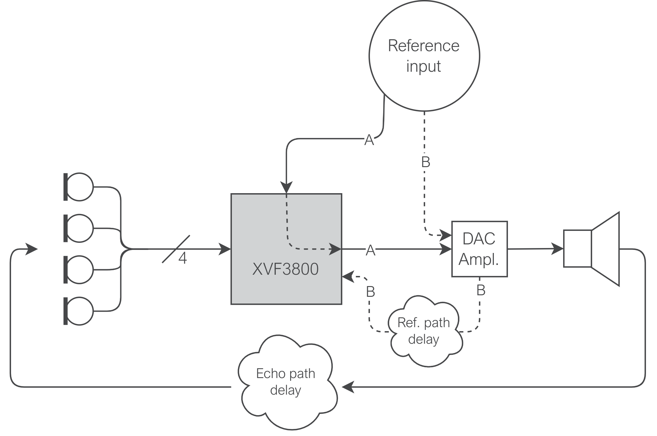
Fig. 23 A more detailed representation of the reference input path for the XVF3800, showing both path A where the signal is routed through the XVF3800 (and any customer-specific pre-processing) before sending to the loudspeaker, and path B where the signal is routed via the loudspeaker before it reaches the XVF3800.#
In an ideal system, the delay between the reference and microphone signals should be at or less than 40 samples.
The AUDIO_MGR_SYS_DELAY parameter allows a configurable delay to be applied to either the microphone signal or the reference signal to achieve this 40 sample difference.
A positive value for this parameter, measured in number of samples, sets a delay on the reference signal; if the delay between microphones and reference is too large, setting this value as positive will reduce this difference. A negative value sets a delay on the microphone signals. Setting this delay to a negative value is the recommended method to correct acausality in the device. Note that this will naturally increase the overall delay from input to output through the device.
To estimate the current causality of the system, use the mic_ref_correlate command provided. To obtain the required signals for this script, set the output mux as follows:
(sudo) xvf_host(.exe) AUDIO_MGR_OP_L 3 <microphone number>
(sudo) xvf_host(.exe) AUDIO_MGR_OP_R 5 0
Note
Causality must be checked for all four microphones, as each of the microphones may have a different echo path delay. Calculate correlation between each microphone and the reference in turn.
Depending on the device sample rate, copy from sources/modules/fwk_xvf/modules/tuning/audio_files the track silence_white_noise_0dbfs_silence_2ch_16khz.wav or silence_white_noise_0dbfs_silence_2ch_48khz.wav; these tracks contain 5s of silence, followed by 10s of 0 dBFS white noise, followed by 5s of silence.
Pass this through the reference input and record the device output in your chosen audio tools, e.g. Audacity.
Save the result as a 2 channel WAV file with the left channel (the post-delay post-gain microphone) as channel 0 and the right channel (the looped-back post-delay post-gain reference signal) as channel 1.
Use this as the input to the script:
python3 xvf_tools.py mic_ref_correlate <input wav file.wav>
A diagram similar to Fig. 24 should be generated.

Fig. 24 Example output of mic_ref_correlate#
Fig. 24 shows a 7 sample delay between microphones and the reference signal.
This system is causal, but only just.
Setting AUDIO_MGR_SYS_DELAY to around -30 will bring the system to the recommended headroom.
This procedure may be repeated after the AUDIO_MGR_SYS_DELAY parameter has been set to verify that the system remains causal and has the desired (less than 40 samples) delay between the reference and microphone inputs.
Ensure that the device is causal for all four microphones.
AEC Operation#
To verify the AEC’s operation, play through the reference input a representative test sample, such as IEEE_269-2010_Male_mono_48_kHz.wav.
Allow the AEC to converge. The convergence of the AEC may be monitored by use of the AEC_AECCONVERGED parameter. This is a read-only parameter. Issuing:
(sudo) xvf_host(.exe) AEC_AECCONVERGED
will present the return value as:
AEC_AECCONVERGED [0|1]
If the returned value is 1, the AEC has converged.
Note
Once this value is set to 1 internally, it is never reset, even if a significant path change or other circumstance forces a significant change in the AEC.
When the AEC reaches convergence (which is expected to take less than 30 seconds), read the AEC coefficients from the device:
(sudo) xvf_host(.exe) (-gf | --get-aec-filter) [filename.bin]
This operation generates 4 separate files <filename.bin>.f0.m[0..3], one per AEC channel. These four files can be analysed in one operation with the read_aec_filter command provided:
python3 xvf_tools.py read_aec_filter <filename.bin>
This should generate a plot as shown Fig. 25.

Fig. 25 Example output of read_aec_filter#
It will also print in the console the peak and mean coefficient values in the frequency domain. To avoid excessive gain through the AEC filter, the mean coefficient value must be below 0 dB for all four microphones. If it is not, reduce AUDIO_MGR_MIC_GAIN to satisfy this. It is recommended to start with a AUDIO_MGR_MIC_GAIN value that gives a peak coefficient value close to 0 dB. The optimal AEC performance may occur with either the peak or the mean coefficient value at 0 dB.
Observe the period between 0 and 100 samples in the time domain. There should be a strong first peak, as shown in Fig. 25. The location of this peak in the time domain should be the same as the previously observed delay between each microphone and the reference input. If this value is significantly above 40 samples, increase AUDIO_MGR_SYS_DELAY to reduce this. If the time domain response starts with a strong peak at the first sample, this could be an indication that your system is acausal - reduce AUDIO_MGR_SYS_DELAY to attempt to bring the full time domain response into view.
AGC Configuration#
The audio pipeline includes an automatic gain controller (AGC) which is applied equally to all four processed outputs from the XVF3800.
This is controlled by four parameters: PP_AGCGAIN, PP_AGCMAXGAIN, PP_AGCDESIREDLEVEL, and PP_AGCONOFF.
PP_AGCGAINboth controls and reports the current multiplicative gain applied to the output beams by the AGC. The value set as the product default is the initial value. When the AGC is active, this value is then dynamically adjusted to attempt to meet the specified output power.
PP_AGCDESIREDLEVELis the parameter that sets this desired output power. The signal power of the free-running beam is measured and compared to the value ofPP_AGCDESIREDLEVEL, andPP_AGCGAINis adjusted to attempt to meet it.
PP_AGCMAXGAINis the maximum value thatPP_AGCGAINmay take in operation.
PP_AGCONOFFdetermines whether the AGC is permitted to adapt or whether the value ofPP_AGCGAINis fixed.
Note
It is important to note that the gain specified by PP_AGCGAIN is always applied, regardless of the value of PP_AGCONOFF; PP_AGCONOFF will only control whether or not this value is permitted to change during operation.
To set appropriate default values for these parameters, set the device’s output mux to output the free-running beam:
(sudo) xvf_host(.exe) AUDIO_MGR_OP_L 6 2
(sudo) xvf_host(.exe) AUDIO_MGR_OP_R 0 0
Initialise the parameters to sensible default values:
(sudo) xvf_host(.exe) PP_AGCGAIN 1.0
(sudo) xvf_host(.exe) PP_AGCMAXGAIN 1000
(sudo) xvf_host(.exe) PP_AGCONOFF 1
Play a near-end signal, such as IEEE_269-2010_Male_mono_48_kHz.wav, at a nominal level and at a nominal distance.
The exact specification for this should be determined by the desired certification.
Allow PP_AGCGAIN to converge on a value, record the device output, and observe the output level.
xvf_tools.py provides the command agc_gain_plot to visualise the current AGC value in real time.
Run the following command:
python3 xvf_tools.py agc_gain_plot --command-help
for usage instructions. This command requires a positional argument with the path to the xvf_host binary, and a few optional arguments, for example --protocol to select the correct communication protocol.
Should the device output be too quiet or too loud for the desired certification specification, alter PP_AGCDESIREDLEVEL and allow PP_AGCGAIN to reconverge.
Once the device output level is as desired, record the stable value of PP_AGCGAIN.
This should then be set as the product’s default value for PP_AGCGAIN.
PP_AGCDESIREDLEVEL can be converted to a target level in dBov or dBm0 as follows:
level_dBov = 10*log10(PP_AGCDESIREDLEVEL)
level_dBm0 = 10*log10(PP_AGCDESIREDLEVEL) + 6
(Note that definitions of dBFS vary between standards as either dBFS == dBov or dBFS = dBov + 3).
To configure PP_AGCMAXGAIN, reduce the near-end signal by 10 dB and repeat the above process, allowing PP_AGCGAIN to converge on a stable value.
This should become the product’s default value for PP_AGCMAXGAIN, and will set the maximum amplification possible by the device.
Check the device performance with quieter speech. If the level is too low, PP_AGCMAXGAIN should be increased. Check the device performance without speech. If background noise is amplified too much when there is no speech, PP_AGCMAXGAIN should be reduced. There is likely to be a compromise between avoiding unwanted amplification of background noise and making very quiet speech sufficiently loud.
Note
It is not recommended to change the AGC time constants. Increasing their speed can result in level fluctuations during speech. For reference, their interactions are described below.
When the AGC gain is being increased (changing from a close speaker to a far-away one):
If
PP_AGCGAINis less thanPP_AGCALPHAFASTGAIN, switch fromPP_AGCALPHASLOWtoPP_AGCALPHAFASTGAINThis will make the AGC gain ramp up faster by using a faster time constant
By default
PP_AGCALPHAFASTGAIN = 0, soPP_AGCALPHASLOWis always used.
When the AGC gain is being decreased (changing from a far-away speaker to a close speaker):
If the instantaneous input power is higher than the smoothed value, switch from
PP_AGCTIMEtoPP_AGCFASTTIMEThis will make the AGC gain ramp down faster by using a faster time constant, and can reduce clipping during sudden loud speech.
By default
PP_AGCTIME = 0.9andPP_AGCFASTTIME = 0.6.
Emphasis#
The rate at which the AEC converges can be optimised by compensating for the spectral characteristics of the reference signal.
If the signal has significant low-frequency energy but proportionally less high-frequency energy, this will affect the AEC’s rate of convergence in the high frequencies, and therefore rate of convergence overall.
An optional high shelf boost may be applied to the microphone inputs using the AEC_AECEMPHASISONOFF parameter.
Play a representative voice sample such as IEEE_269-2010_Male_mono_48_kHz.wav as the reference audio and capture the post-gain, post-delay reference signal:
(sudo) xvf_host(.exe) AUDIO_MGR_OP_L 5 0
(sudo) xvf_host(.exe) AUDIO_MGR_OP_R 0 0
Perform a Fourier transform using Audacity, or equivalent, and identify the peak magnitude value. Compare this to the magnitude of the signal at 8 kHz. It is expected that the magnitude of the signal at 8 kHz will be less than the peak magnitude.
If they have similar magnitudes, set AEC_AECEMPHASISONOFF to 0.
If the difference in magnitudes is around or greater than 8 dB, set AEC_AECEMPHASISONOFF to 1.
If the difference is around or greater than 40 dB, set AEC_AECEMPHASISONOFF to 2.
The impact of tuning this parameter may be observed by measuring the AEC convergence speed. From a fresh restart, set the following parameters to output clear AEC residuals from a selected pair of microphones:
(sudo) xvf_host(.exe) PP_MIN_NS 1.0
(sudo) xvf_host(.exe) PP_MIN_NN 1.0
(sudo) xvf_host(.exe) PP_ECHOONOFF 0
(sudo) xvf_host(.exe) PP_NLATTENONOFF 0
(sudo) xvf_host(.exe) PP_AGCONOFF 0
(sudo) xvf_host(.exe) AUDIO_MGR_OP_L 7 [microphone number]
(sudo) xvf_host(.exe) AUDIO_MGR_OP_R 7 [microphone number]
Play a representative voice sample such as IEEE_269-2010_Male_mono_48_kHz.wav as the reference input on a loop for around 60 seconds.
Capture the device output for this whole period (around 60 seconds); these will be the AEC residuals generated.
Observe the spectrogram of the output signal and verify that the AEC converges evenly for all frequencies; that is to say, over the time that the AEC is converging, the high frequencies should converge as quickly as the low frequencies. It should not be observed that the high frequencies converge quicker or slower.
MGSCALE#
The PP_MGSCALE parameter controls additional noise suppression that is applied during periods of far-end activity.
The aim is to optimise speech clarity output from the device during periods of stationary far-end activity, while also ensuring that there is good echo suppression in periods of non-stationary far-end activity.
An undesirable scenario may arise if there exists unintended low-level noise in the reference signal, from e.g. ADC noise in the reference path.
In this scenario, the low-level noise may be erroneously detected as far-end speech; the device may then incorrectly detect that double-talk is present and overly suppress near-end speech.
The PP_MGSCALE parameter configures where this trade-off between far-end echo suppression and near-end signal clarity lies.
To tune both the min and max values for the PP_MGSCALE parameter, set the following:
(sudo) xvf_host(.exe) PP_GAMMA_E 1.0
(sudo) xvf_host(.exe) PP_GAMMA_ENL 1.0
(sudo) xvf_host(.exe) PP_GAMMA_ETAIL 1.0
(sudo) xvf_host(.exe) PP_ECHOONOFF 1
(sudo) xvf_host(.exe) PP_NLATTENONOFF 0
(sudo) xvf_host(.exe) PP_MIN_NS 1.0
(sudo) xvf_host(.exe) PP_MGSCALE 1 1 1
(sudo) xvf_host(.exe) AUDIO_MGR_OP_L 6 3
(sudo) xvf_host(.exe) AUDIO_MGR_OP_R 0 0
Play a representative far-end signal such as IEEE_269-2010_Male_mono_48_kHz.wav on loop as the reference input.
Provide a just-noticeable stationary near-end noise signal, such as white noise.
This should be played at a very low level from a second loudspeaker/source within the room.
Observe the device output, including the spectrogram.
Increasing the value of max - the first parameter to PP_MGSCALE - will reduce the amount of residual echo.
Increase max until no further improvements are observed.
Note
A typical value for max will be between 100 and 1000.
Set min to the derived value for max so that the two are equal.
Depending on the device sample rate, copy from sources/modules/fwk_xvf/modules/tuning/audio_files the track silence_2ch_16khz.wav or silence_2ch_48khz.wav.
Play the silence track into the reference input, and provide a representative near-end signal such as IEEE_269-2010_Male_mono_48_kHz.wav.
Subjectively listen to the device output.
There may be stationary noise present on the far-end, which may cause erroneous echo suppression and therefore erroneous speech distortion.
Reducing min can reduce near-end speech distortion at the cost of reduced stationary noise suppression where stationary noise is present in the far-end signal.
FMIN_SPEINDEX#
PP_FMIN_SPEINDEX is a parameter that controls the frequency-dependent suppression that the device performs in a double-talk environment.
In the case of double-talk, the device’s output will suppress frequencies below the value of PP_FMIN_SPEINDEX more than frequencies above the value of PP_FMIN_SPEINDEX
Set the following to output clear AEC residuals from a selected pair of microphones:
(sudo) xvf_host(.exe) PP_MIN_NS 1.0
(sudo) xvf_host(.exe) PP_MIN_NN 1.0
(sudo) xvf_host(.exe) PP_ECHOONOFF 0
(sudo) xvf_host(.exe) PP_NLATTENONOFF 0
(sudo) xvf_host(.exe) PP_AGCONOFF 0
(sudo) xvf_host(.exe) AUDIO_MGR_OP_L 7 [microphone number]
(sudo) xvf_host(.exe) AUDIO_MGR_OP_R 7 [microphone number]
Depending on the device sample rate, copy from sources/modules/fwk_xvf/modules/tuning/audio_files the track white_noise_0dbfs_2ch_16khz.wav or white_noise_0dbfs_2ch_48khz.wav.
Play through the reference input the white noise signal, and capture the AEC residuals that are output from the device.
Take a Fourier transform of the interval from 40 - 60 seconds, and plot the magnitude of the coefficients.
It is expected that there will be an identifiable “peak” in this spectrum in the lower frequencies, which drops back down into the higher frequencies.
Set PP_FMIN_SPEINDEX to the highest frequency on this initial peak after which there is no further decrease in the amplitude spectrum when compared to higher frequencies; in the spectrum shown in Fig. 26 for example, PP_FMIN_SPEINDEX should be set to around 1200 (1.2 kHz), as up to this point the amplitudes for frequencies on this peak are greater than any other higher frequency; however, at 5.5 kHz there exists another peak which has greater amplitude than frequencies greater than ~1.2 kHz.
If the spectrum appears roughly flat from around 500 Hz onwards, with no significant decrease in amplitude at higher frequencies, leave PP_FMIN_SPEINDEX at its default value of 593.75 Hz.
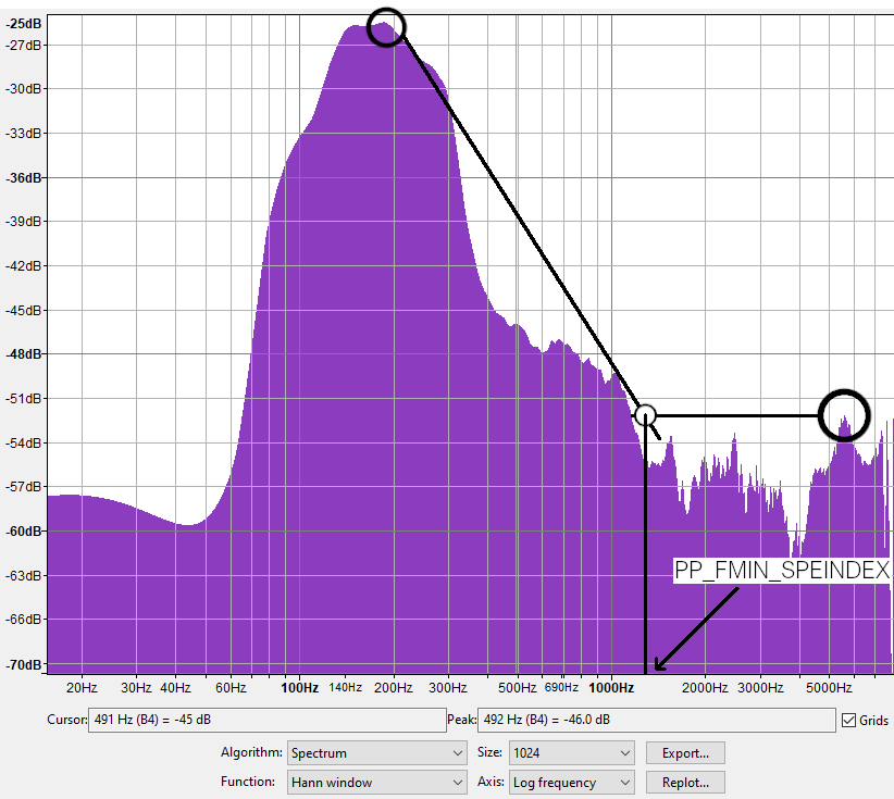
Fig. 26 Illustration of the method by which PP_FMIN_SPEINDEX may be determined#
Tuning the Non-Linear Model#
Non-linear Echo#
It is likely that in all devices, regardless of the quality of the audio design, there will exist some non-linearities. The aim of non-linear estimation is to model the remaining residual echo after linear echo content (including tail echoes) has been removed. This is achieved in the XVF3800 by use of a self-training non-linear model.

Fig. 27 Example non-linear matrix plot.#
It is very important to ensure that non-linear model training takes place in a silent environment, and that the environment is ideally anechoic; the RT60 of the environment for example should be as low as possible, and absolutely below 0.3s. As can be seen in Fig. 27, it is important that the observed distortion should increase as the output level increases. If the distortion is high/higher at lower levels, it may indicate that the room is too noisy for tuning, or that the microphone is clipping and AUDIO_MGR_MIC_GAIN needs to be reduced.
If the distortion spectrum shape is similar across output levels, it indicates low distortion from the loudspeaker and housing. In this case, non-linear echoes are likely to have a small effect on echo cancellation.
Note
The XVF3800 provides an estimate of the current RT60 value of its environment. This is obtained via the AEC_RT60 command.
It is also important to minimise/eliminate any path changes in the environment during non-linear tuning, such as movement of people or objects. This tuning step is very deliberately placed after any gain or pre-processing adjustments have been made. Any changes to the device’s gain structure, including changing any filtering, will require retuning of the non-linear model.
The tuning process should be run two or three times, and the results compared. If the plots are significantly different, this implies that non-linearities within the system are changing with time. This can indicate that the coupling between the loudspeaker and the microphones is varying over time, that there is time-dependent noise in the system, or that the external environment is changing with time (e.g. not totally silent).
Tuning Setup for Non Linear model#
This tuning process is somewhat lengthy, and so a set of files and associated training script have been provided for this tuning step. The process differs slightly depending on whether the host device can play audio directly through the device (as in Fig. 28) or whether a 3rd computer is required (as in Fig. 29).
Local Device#
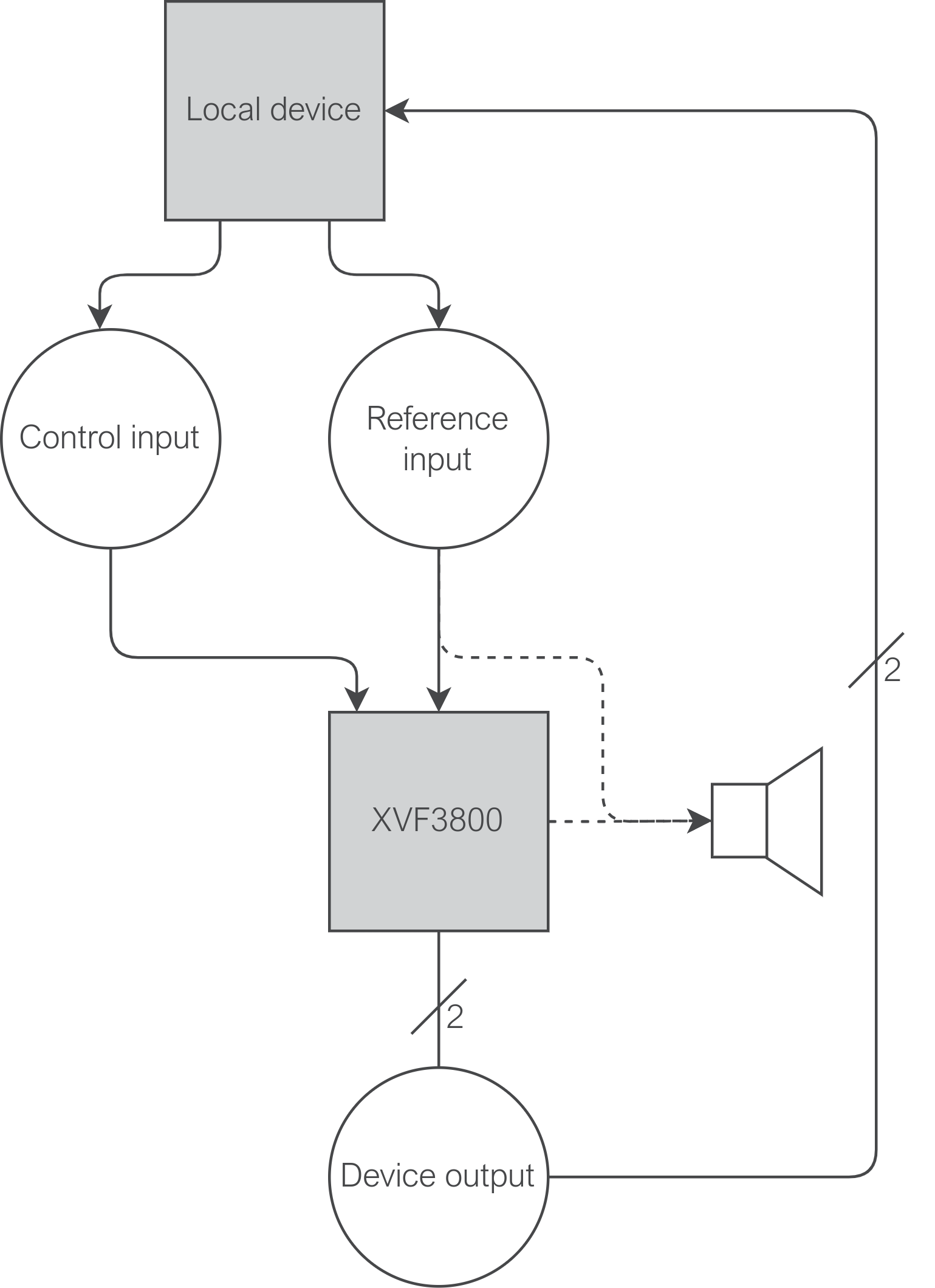
Fig. 28 Top-level diagram of a system where the audio host and control host are the same device#
For this route, it is assumed that the host device is also the device that is providing audio to the XVF3800, through e.g. an I2S interface for the XVF3800 INT-Device variant or USB interface for the XVF3800 UA device.
Via xvf_tools.py, it is possible to run the command nl_model_training, which executes all the necessary steps to train the non-linear model.
Run the command nl_model_training as:
python3 xvf_tools.py nl_model_training <host_app> [--protocol {i2c,spi,usb}]
where <host_app> is the path to the xvf_host file, this can be an absolute path or a path relative to the current working directory.
This will generate an output file with the default name of nlmodel_buffer_override.bin.r16.c40.
Copy this file to sources/app_xvf3800/nl_model_gen/nlmodel_bin and rerun the build process to generate a binary with this non-linear model set as default.
A different output file can be selected by using the optional arguments --output and --output_dir.
Refer to the docstring for this script for further guidance.
Remote Device#
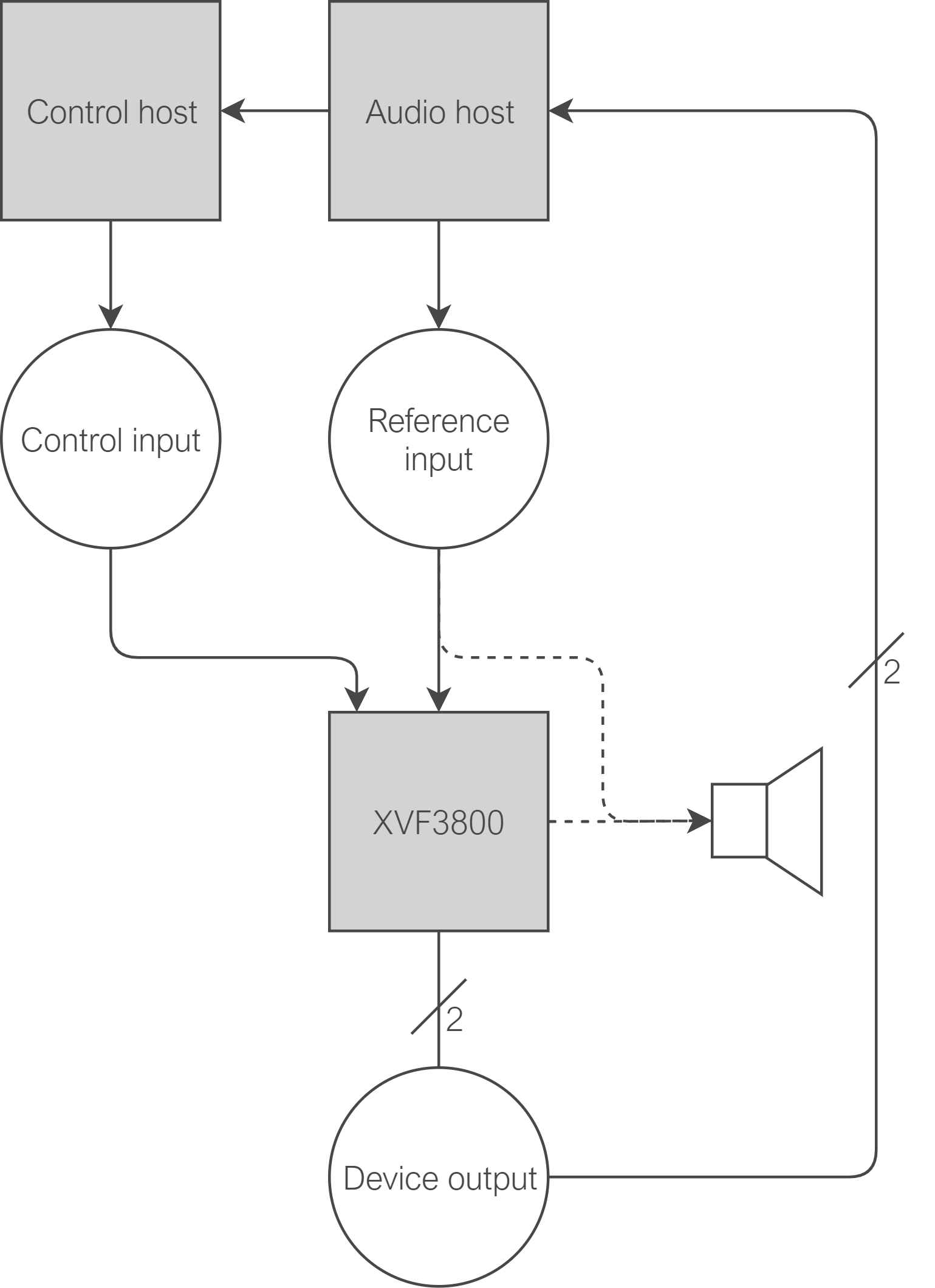
Fig. 29 Top-level diagram of a system where the audio host and control host are separate devices#
For this route, it is assumed that a 3rd device is acting as the audio source (here termed the “audio host”).
Therefore, to issue control commands, it is necessary to remotely connect to the “control host” (assumed to be a Raspberry Pi) over SSH. This can be done using the command remote_nl_model_training from xvf_tools.py.
Locate the host application binaries on the audio host; these should be located at host_v<version>/rpi in the release package.
Ensure that the audio host has passwordless access to the control host over SSH; this may be achieved by generating an SSH key pair and adding the public key to ~/.ssh/authorized_keys on the control host.
This script requires that the audio host have an installation of sox in its path, as well as Python3 with matplotlib and asyncssh installed via Pip.
Ensure that the default loudspeaker and microphone on the audio host are set as the device to be tuned.
From the audio host, run the script as:
python3 xvf_tools.py remote_nl_model_training <control host IP address> <host application binary path on the audio host>
Once the script has run, locate the generated nlmodel_buffer_override.bin.r16.c40 and corresponding plot in the src.autogen directory.
Copy this file to sources/app_xvf3800/nl_model_gen/nlmodel_bin and rerun the build process to generate a binary with this non-linear model set as default.
A different output file can be selected by using the optional arguments --output and --output_dir.
Refer to the docstring for this script for further guidance.
Support for multiple products#
The XVF3800 allows to have different nlmodel binary files for different build configurations. If the users have multiple .bin.r16.c40 files,
it can associate them to a specific build configuration by overwriting the CMake variable NL_MODEL_BIN,
for example if a file nlmodel_buffer_new_override.bin.r16.c40 must be included, the following line must be added in sources/app_xvf3800/CMakeLists.txt:
set(NL_MODEL_BIN nlmodel_buffer_new_override.bin.r16.c40)
Echo Suppression#
With the non-linear model trained, we are now in a position to balance echo suppression against speech distortion. Five tuning parameters are relevant for this section:
PP_DTSENSITIVE: This parameter sets a balance between double-talk performance and echo suppression.PP_ECHOONOFF: This parameter sets whether echo suppression is enabled or disabled overall.PP_NLATTENONOFF: This parameter sets whether non-linear echo suppression is enabled or disabled.PP_GAMMA_E: This parameter adjusts the oversubtraction factor for direct and early echo suppression.PP_GAMMA_ENL: This parameter adjusts the oversubtraction factor for non-linear echo suppression.PP_GAMMA_ETAIL: This parameter adjusts the oversubtraction factor for echo tail suppression.
For the PP_GAMMA_* parameters, a value of 1.0 indicates that the device has correctly estimated and suppressed the respective echo classes from the output. Increasing these values increases the amount of suppression, and indicates that the device has underestimated the amount of echo in the outputs. It is unlikely for the device to overestimate the amount of echo, and so it is not advised to set these parameters to values below 1.0. A typical range for these parameters is between 1.0 and 1.4.
Increasing these parameters will always affect the quality of the speech signal. Attempt in the first instance to create as good an acoustic design as possible, with a linear loudspeaker, good quality microphones, and a maximally non-linear enclosure. This will reduce or eliminate the need to adjust these values, and will present a more performant device.
PP_DTSENSITIVE#
PP_DTSENSITIVE allows some control over the balance struck between double-talk performance and echo suppression, including the use of an optional near-end speech detector. This is summarised in Fig. 30; as echo suppression increases, double-talk performance will tend to decrease as more near-end is suppressed.

Fig. 30 Illustration of relationship between PP_DTSENSITIVE value and echo suppression#
The tuning process for this parameter is not straightforward. A recommended approach is to start with this parameter set to 0, and attempt to then tune the rest of the echo suppression parameters. If insufficient echo suppression is achieved before setting these parameters unacceptably high (above around 1.4), increase PP_DTSENSITIVE and attempt to retune. If this results in unacceptable double-talk performance, lower PP_DTSENSITIVE and attempt to retune. Find a balance between acceptable echo performance and double-talk performance by balancing settings for PP_DTSENSITIVE and the PP_GAMMA_ parameters.
PP_GAMMA_E and PP_GAMMA_ENL#
The objective of tuning these two parameters is the removal of echoes to pass e.g. Teams EQUEST and ECC specifications. Ensure that this tuning step takes place in an anechoic or mildly reverberant environment, with an RT60 less than 0.3 s.
Set the device as follows to output the autoselect beam in the left channel and the AEC residual signal for microphone 0 in the right channel:
(sudo) xvf_host(.exe) PP_AGCONOFF 0
(sudo) xvf_host(.exe) PP_MIN_NN 1.0
(sudo) xvf_host(.exe) PP_MIN_NS 1.0
(sudo) xvf_host(.exe) PP_GAMMA_E 1.0
(sudo) xvf_host(.exe) PP_GAMMA_ENL 1.0
(sudo) xvf_host(.exe) PP_GAMMA_ETAIL 1.0
(sudo) xvf_host(.exe) AUDIO_MGR_OP_L 6 3
(sudo) xvf_host(.exe) AUDIO_MGR_OP_R 7 0
Play through the reference input a representative signal, such as IEEE_269-2010_Male_mono_48_kHz.wav.
Allow the AEC to converge.
After 30 seconds, play a representative near-end signal in addition to the far-end signal, to place the device into a representative double-talk scenario.
Listen to the device’s output.
Starting with the default value of 1.0, adjust PP_GAMMA_E to make the trade-off between double-talk performance and echo suppression.
Should the value of PP_GAMMA_E need to exceed around 1.4 to achieve acceptable performance, consider adjusting PP_GAMMA_ENL instead, especially if the echoes that remain in the AEC residual signal are of a non-linear nature.
To identify the nature of the echoes that remain, listen to the AEC residual signal and categorise the residual echoes as follows:
Linear residual echoes: Echoes can be understood at a low level but do not sound distorted and do not sound reverberated. Controlled by
PP_GAMMA_E.Tail echoes: Echos sound reverberated, with no direct component. This will sound like indistinct reverb, but with no clear original source. Controlled by
PP_GAMMA_ETAIL.Non-linear echoes: Echoes sounds very distorted, with no discernable e.g. speech content. Controlled by
PP_GAMMA_ENL.
Note however that echo suppression is applied after the point where the AEC residual signals are tapped, and so changes to the PP_GAMMA_ parameters will not be reflected in the AEC residual signals.
These signals are useful therefore for categorising the kinds of echo present, but the device’s output should be used to observe qualitative changes in echo suppression.
PP_GAMMA_ETAIL#
To tune this parameter, repeat the above procedure in a moderately reverberant room (with an RT60 between 0.3 and 0.9s). Clear tail echoes should be observed in the residual signal, and these tail echoes should be improved by adjustment of PP_GAMMA_ETAIL. Adjust this parameter, making a trade-off between double-talk performance and echo suppression.
Noise Suppression#
Two parameters control suppression of stationary and non-stationary noise in the device output: PP_MIN_NS and PP_MIN_NN respectively.
These parameters take values between 0 and 1, representing the multiplicative attenuation of these two noise sources. For example, PP_MIN_NS is set to 0.15 by default, representing a roughly 15 dB attenuation of stationary noise in the device output.
It is recommended that PP_MIN_NN is set by default to 0.51 or higher, representing at most a 6 dB attenuation of non-stationary noise in the device output. Reducing this value further may have significant impact on near-end speech quality, especially in reverberant environments.
To tune these parameters, set the device as follows:
(sudo) xvf_host(.exe) PP_AGCONOFF 0
(sudo) xvf_host(.exe) PP_MIN_NS 0.15
(sudo) xvf_host(.exe) PP_MIN_NN 0.51
(sudo) xvf_host(.exe) AUDIO_MGR_OP_L 6 3
(sudo) xvf_host(.exe) AUDIO_MGR_OP_R 0 0
Play a representative near-end signal, such as IEEE_269-2010_Male_mono_48_kHz.wav. Subjectively evaluate the device output, first noting the presence of stationary noise. Reduce PP_MIN_NS to suppress this noise further. Reducing this parameter may introduce or increase distortion in near-end speech; ensure that a balance is struck between speech quality and stationary noise suppression.
Note next the presence of non-stationary noise. Reduce PP_MIN_NN to suppress this noise further. As with PP_MIN_NS, reducing this parameter may introduce distortion in near-end speech, particularly in reverberant environments. Ensure that an appropriate balance is struck between speech quality and non-stationary noise suppression. Reducing the value of PP_MIN_NN to 0.5 or below will trigger additional non-stationary noise supression.
ATTNS#
The ATTNS parameters (PP_ATTNS_MODE, PP_ATTNS_NOMINAL, and PP_ATTNS_SLOPE) control an additional reduction in AGC gain during non-speech periods.
Collectively, they attempt to combat an undesirable side-effect of the use of an AGC - the tendency to noticeably amplify noise in non-speech periods when the near-end speech signal is quiet.
The Zoom Rooms specification test 7.4.3 (as of writing, last issued in October 2019) sets limits on how amplified this non-speech noise may be when the AGC is at a high gain compared to the noise level when the AGC is at a low gain.
Therefore, attenuating noise at a greater strength when the AGC is at a high gain may reduce this noise and achieve better performance in these tests.
The overall behaviour of the ATTNS may be selected with the PP_ATTNS_MODE parameter, which both functions as a specifier of whether the ATTNS is in use and whether bias is applied against selecting beams with high noise as the autoselected beam.
0 - The ATTNS is off
1,2 - The ATTNS is on
Note
Setting ATTNS mode to 1 and 2 has the same effect.
When the ATTNS is on, PP_ATTNS_NOMINAL and PP_ATTNS_SLOPE control the additional attenuation proportional to:

where AGCGAIN_INIT is the value of PP_AGCGAIN set as the default value at initialisation, and AGCGAIN_CURRENT is the current value of PP_AGCGAIN.
Because of this module’s relationship with the current value of PP_AGCGAIN, this module has no effect when PP_AGCONOFF is set to 0.
Because both the Teams v4 and Zoom Rooms specifications specify this suppression as a ratio between the noise at a nominal speech level and the noise at a low speech level, it may be required to tune both of these parameters in parallel; changing one may have an effect on the required value for the other, and vice-versa.
To tune these parameters, ensure that PP_AGCGAIN and PP_AGCMAXGAIN are tuned correctly, then perform the following:
ATTNS_NOMINAL#
Issue the following to set appropriate default values for this tuning step:
(sudo) xvf_host(.exe) PP_AGCONOFF 1
(sudo) xvf_host(.exe) PP_ATTNS_MODE 1
(sudo) xvf_host(.exe) PP_ATTNS_NOMINAL 1.0
(sudo) xvf_host(.exe) PP_ATTNS_SLOPE 0.0
Play a representative near-end signal at a nominal level, such as the ITU P.501 7.3.2 reference signal FB_male_female_single-talk_seq.wav.
This signal can be found in the Speech Signals/Test_Signals_Clause 7/Speech Test Signals Clause 7.3 & 7.4/English_FB_clause_7.3/ directory of the ITU P.501 download package.
Setting ATTNS_NOMINAL > 1 should provide more noise suppression during silence. With a particular specification in mind, increase this value until desired/specified noise suppression is achieved during the test conditions. For example, this could be done by monitoring average A-weighted noise during the period 1s after the end of a sentence in the reference signal and ensuring that it is within satisfactory bounds. This is usually specified as a ratio between this value and the averaged value obtained with the near-end signal at a range of low levels.
ATTNS_SLOPE#
Issue the following to set appropriate default values for this tuning step:
(sudo) xvf_host(.exe) PP_AGCONOFF 1
(sudo) xvf_host(.exe) PP_ATTNS_MODE 1
(sudo) xvf_host(.exe) PP_ATTNS_NOMINAL <default found in previous step>
(sudo) xvf_host(.exe) PP_ATTNS_SLOPE 1.0
Play a representative near-end signal at a nominal level, such as the ITU P.501 7.3.2 reference signal FB_male_female_single-talk_seq.wav.
Setting ATTNS_SLOPE > 1.0 provides additional noise suppression during silence, proportional to an increased AGC gain. With a particular specification in mind, increase this value until desired/specified noise suppression is achieved during the test conditions.
For example, this could be done by monitoring average A-weighted noise during the period 1 second after the end of a sentence in the reference signal and ensuring that it is within satisfactory bounds; this is usually specified as a ratio between this value and the averaged value obtained with the near-end signal at a range of low levels.
Path Change Detection#
The XVF3800 provides a facility to detect significant path changes in the device’s environment such as handling the device and moving to a different location using a module called the Path Change Detector (PCD). If a path change is detected, heavy near-end suppression during far-end activity is applied in order to allow the AEC time to reconverge to its new environment. If the device incorporating the XVF3800 is not intended for a mobile application (for example, a wall-mounted sound bar), then detection of path changes is not necessary.
The PCD may be tuned using the AEC_PCD_COUPLINGI, AEC_PCD_MINTHR, and AEC_PCD_MAXTHR parameters.
AEC_PCD_COUPLINGI controls the rate of detection of a path change, and takes a value between 0 and 1. Setting this to a low value encourages fast detection of path changes at the increasing risk of false positives during double-talk. Setting this to a high value slows detection of path changes (and increases the detection threshold, meaning some small changes may be missed) but reduces the risk of false positives in double-talk. Setting this parameter to a value outside of the range 0 to 1 will disable the PCD.
Tuning of this parameter is necessarily very situation- and product-dependent. Monitoring of the AEC_AECPATHCHANGE parameter can allow insight into whether a path change has been detected; reading a 1 value implies that a path change has recently been detected and that the device output is currently heavily suppressed during far-end activity. This parameter will reset to 0 after the AEC has reconverged.
AEC_PCD_MINTHR and AEC_PCDP_MAXTHR are used to set sensitivity thresholds, and their use depends on the overall Echo Return Loss Estimate (ERLE) of the device.
For devices with a high ERLE (implying a high ratio between the provided reference signal and the resultant AEC residual, and therefore high cancellation), use AEC_PCD_MINTHR to limit the lower bound. Decreasing this value from its default of 0.02 will increase the sensitivity of the PCD.
For devices with a low ERLE, use AEC_PCD_MAXTHR to limit the upper bound. Decrease this value from its default of 0.2 to increase the sensitivity of the PCD.
Output equalization#
The XVF3800 has an equalizer that can be used to adjust the output frequency response, should it not meet the limits in a Teams/Zoom spec. This may be needed to compensate for the frequency response of the microphones and their housing. The equalizer is applied in the frequency domain before the AGC.
xvf_tools.py provides the command ploteq to generate the coefficients. To run the script, run the following command:
python3 xvf_tools.py ploteq
The script produces a GUI shown in the picture below.

The user must first select in the lower left corner:
the band appropriate for the device: wideband or superwideband
the desired resolution: “octave bands” gives an 8 band equalizer with control points at one octave intervals [62.5, 125, 250, 500, 1000, 2000, 4000, 8000], while “1/3 octave bands” give finer resolution, with a 22 band equalizer with control points at 1/3 octave intervals.
The user can click on the GUI to update the frequency gains and to achieve the desired filter. The coefficients can be exported using the Export command in the lower right corner.
When the file with the desired coefficients is ready, it can be written to the device using the command:
(sudo) xvf_host(.exe) --set-eq-filter eq.bin
where eq.bin is the file exported by the ploteq command.
The user can override the default equalization filter included in the build. To do this:
rename the
eq.binfile generated above aseq_filter_override.bincopy it to folder
sources/app_xvf3800/eq_filter_gen/eq_filter_bin/rerun the build process to create a binary with the new equalization filter set as default.
The filter can be read using the command:
(sudo) xvf_host(.exe) --get-eq-filter eq.bin
and it can be visualised using the Import command in the GUI of the ploteq command.
Changing Default Parameter Values#
The default parameters set at start-up are loaded from the file defaults.c in sources/app_xvf3800/src/default_params.
In this file the values are included from some header files auto-generated at compile time.
The values used in defaults.c must be updated using the YAML files stored in sources/app_xvf3800/autogeneration/yaml_files/settings_and_defaults/.
The XVF3800 supports separate default values for different products.
In the sources/app_xvf3800/autogeneration/yaml_files/settings_and_defaults/ there is a subfolder for each product specifier, for example the default values for
the XK-VOICE-SQ66 development kit are stored in the product subfolder.
Note
Any default value set outside the YAML files will be overwritten at compile time.
In the product directory five files used to generate defaults.c are present:
mic_geometries.yaml
control_param_values.yaml
gpi_config.yaml
gpo_config.yaml
usb_param_values.yaml
Warning
All the parameters in the files above must be set; failure to do this can lead to unexpected behaviour of the device, such as uninitialized start-up values.
Note
PP_MGSCALE provides three values when queried through the host application, but only requires two to be set here - max and min.
mic_geometries.yaml contains the coordinates for each of the 4 mics for both the linear and square/rectangular geometries.
An example of the values is below:
LINEAR_GEOMETRY:
  - MIC0: ( -0.04995f,    0.00f,      0.00f )
  - MIC1: ( -0.01665f,    0.00f,      0.00f )
  - MIC2: ( 0.01665f,     0.00f,      0.00f )
  - MIC3: ( 0.04995f,     0.00f,      0.00f )
SQUARECULAR_GEOMETRY:
  - MIC0: ( 0.0333f,      -0.0333f,   0.00f )
  - MIC1: ( 0.0333f,      0.0333f,    0.00f )
  - MIC2: ( -0.0333f,     0.0333f,    0.00f )
  - MIC3: ( -0.0333f,     -0.0333f,   0.00f )
The user must update the values to match the geometry used in their target application. The default configurations shown above are those supported by the XK-VOICE-SQ66 development kit.
control_param_values.yaml lists all the control parameters which can be configured.
An example of a parameter with a default value is below:
PP_RESID:
  - cmd: PP_AGCONOFF
    default_value: on
The parameters in the file are organized into arrays, and each array contains all the parameters related to a particular control resource ID.
The parameter name is stored in the cmd key and the default value in the default_value key.
In the example above, the default value of the parameter PP_AGCONOFF belonging to the PP_RESID is on.
The number of values and type of each parameter may vary from command to command.
It is advised to look up the command information in the tables in the Control Commands Appendix and to follow the format of
the original default values in order to set the values properly.
gpi_config.yaml stores all the settings of the GPI pins.
The XVF3800 has 2 configurable GPI pins and the following parameters can be modified:
active_level: 0 for low and 1 for high
event_config: four types of events are supported:
EdgeNone: no event is detected on either edge
EdgeFalling: an event is detected on the falling edge (high to low transition)
EdgeRising: an event is detected on the rising edge (low to high transition)
EdgeBoth: one event is detected on the rising edge and one on the falling edge
The default configurations of the GPI pins are below:
# Exactly GPIO_NUM_INPUT_PINS pins should be defined here

PIN0:
  active_level: 1
  event_config: EdgeNone
PIN1:
  active_level: 1
  event_config: EdgeNone
gpo_config.yaml lists the settings of all the GPO pins and ports.
The XVF3800 device has one 8-bit port designated for GPO. Only five of the eight are pinned out, and three pins are required for the device to operate normally, leaving the remaining two pins available for user modification.
These pins are number 6 and 7, and they are used to control the LEDs in the default firmware.
In the file each port must be listed; the XVF3800 only implements PORT0. For each port an array of eight pins must be defined and each pin has the following configurable settings:
pin_number: this value shouldn’t be modified
active_level: 0 for low and 1 for high
output_duty_percent: Pulse-width modulation (PWM) duty cycle specified as a percentage
flash_serial_mask: serial flash mask where each bit specifies the GPO pin state for a 100 ms time period interval
The default configurations of the GPO port and pins are below:
PORT0:
  # UNUSED: NOT PINNED OUT
  - pin_number: 0
    active_level: 1
    output_duty_percent: 0
    flash_serial_mask: 0xFFFFFFFF
  # UNUSED: NOT PINNED OUT
  - pin_number: 1
    active_level: 1
    output_duty_percent: 0
    flash_serial_mask: 0xFFFFFFFF
  # UNUSED: NOT PINNED OUT
  - pin_number: 2
    active_level: 1
    output_duty_percent: 0
    flash_serial_mask: 0xFFFFFFFF
  # GPO_DAC_RST_N_PIN
  - pin_number: 3
    active_level: 1
    output_duty_percent: 100
    flash_serial_mask: 0xFFFFFFFF
  # GPO_SQ_nLIN_PIN
  - pin_number: 4
    active_level: 1
    output_duty_percent: 0
    flash_serial_mask: 0xFFFFFFFF
  # GPO_INT_N_PIN
  - pin_number: 5
    active_level: 1
    output_duty_percent: 100
    flash_serial_mask: 0xFFFFFFFF
  # GPO_LED_RED_PIN
  - pin_number: 6
    active_level: 0
    output_duty_percent: 0
    flash_serial_mask: 0xFFFFFFFF
  # GPO_LED_GREEN_PIN
  - pin_number: 7
    active_level: 0
    output_duty_percent: 0
    flash_serial_mask: 0xFFFFFFFF
usb_param_values.yaml lists the settings of the USB port.
The default configuration of the USB port is shown below:
VENDOR_ID: 0x20B1
PRODUCT_ID_IO_16KHZ: 0x4F01
PRODUCT_ID_IO_32KHZ: 0x0000
PRODUCT_ID_IO_48KHZ: 0x4F00
MANUFACTURER_STR: "XMOS"
PRODUCT_STR: "XVF3800 Voice Processor"
SERIAL_NUMBER_STR: "000000"
CONTROL_INTERFACE_STR: "XMOS Control"
HID_INTERFACE_STR: "XMOS HID"
DFU_FACTORY_INTERFACE_STR: "XMOS DFU Factory"
DFU_UPGRADE_INTERFACE_STR: "XMOS DFU Upgrade"
DEFAULT_BIT_DEPTH_IN: "16"
DEFAULT_BIT_DEPTH_OUT: "16"
Note
When the default parameters are changed, it is necessary to rebuild the application and reload onto the XVF3800 as described in the following section. See Building an Executable.
Warning
The process to rebuild the application does not check each parameter’s value to ensure that it falls within its valid range. A change to a parameter value that falls outside of its valid range may result in undefined behaviour.
The XVF3800 build system supports multiple sets of default values. If a new product with different default values must be built, do the following:
Create a new folder in
sources/app_xvf3800/autogeneration/yaml_files/settings_and_defaults/, for examplenew_productCopy the YAML files in
sources/app_xvf3800/autogeneration/yaml_files/settings_and_defaults/productinto the new folderUpdate the values in the new YAML files
Add or modify a build configuration as described in Adding or Modifying Build Configurations section of the Programming Guide
Overwrite the CMake variable
PRODUCT_DEFAULT_SPECIFIER, for example by adding insources/app_xvf3800/CMakeLists.txtthe following:set(PRODUCT_DEFAULT_SPECIFIER new_product)