sliceKIT Development Board Tutorial
Introduction
This tutorial provides an introduction to XMOS sliceKIT development boards.
NOTE: Before starting it you should complete the xTIMEcomposer Studio - Simulator Tutorial, which shows you how to create a PWM project that is used as the starting point of this tutorial.
The tutorial shows you how to:
- Set up the sliceKIT hardware
- Run the PWM application on your sliceKIT board
- Dim the LEDs up and down
- Add printing
- Add an I2C interface to read the temperature
- Next steps
We recommend that you follow the tutorial step-by-step. If you need to download the source code for the examples discussed it is available from xmos.com sliceKIT Development Board Tutorial Code Examples.
Set up the sliceKIT hardware
To follow this tutorial you need the following sliceKIT board and cards
- XP-SKC-L2 sliceKIT Core Board
- XA-SK-GPIO GPIO sliceCARD
- xTAG-2 Debug Adapter
All these boards are available in the sliceKIT Starter Kit - see www.xmos.com/slicekit.
Details on mapping between pins on the Core Board and ports is available in the sliceKIT Core board documentation.
Connect up the boards
- Connect the xTAG Adapter to the XSYS connector on the sliceKIT Core board.
- Connect the xTAG-2 to the xTAG adapter.
- Connect the GPIO sliceCARD to the sliceKIT Core board using the connector marked with the SQUARE.sliceKIT core board with xTAG and GPIO sliceCARD

Run the PWM application on your sliceKIT board
In the xTIMEcomposer Studio - Simulator Tutorial, the PWM application is run on the xCORE simulator on your PC or Mac. You can quickly change the Run Configuration to execute the application on your sliceKIT development board.
Run your application
- Open the workspace you used for the xTimeComposer Studio Tutorial – Simulator.
- Select Run > Run Configurations.
- Change the Device Options from simulator to hardware.
The Target should be shown as XMOS XTAG-2 connected to L1[0..1].
Run Configuration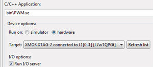
xTIMEcomposer uses JTAG to load the application directly into the internal SRAM in the xCORE multicore microcontroller. The SRAM is a fast, single cycle memory and does not include caches, which makes all memory accesses deterministic.
Loading directly into SRAM is used during development, as it provides the fastest mechanism for loading code into the device. In production, xCORE devices usually boot from SPI flash. xTIMEcomposer includes a flash programming utility that can be used by creating a Flash Configuration in the same way as a Run Configuration - see Run > Flash.
- Click Run.
After a short delay during which the sliceKIT Core Board is booted over High Speed USB and JTAG, all four LEDs on the GPIO sliceCARD light up at 50% brightness (50% duty cycle).
Dim the LEDs up and down
In the xTIMEcomposer Studio - Simulator Tutorial, you created a basic pwm_controller task to initialize the period and duty cycle of the pwm_tutorial_example task via a channel.
The pwm_tutorial_example task also accepts updates to the duty cycle value at any time. You can therefore enhance the pwm_controller task to control the duty cycle of the PWM over time, thereby varying the brightness of the LEDs.
This section shows you how to:
- Start with LEDs off and increase the brightness gradually to 100%.
- Once 100% brightness is reached, decrease brightness gradually to 0%.
- Put this function into a loop so that the LEDs continuously increase and decrease in brightness.
NOTE: The LEDs on the GPIO sliceCARD are active-low, which means a duty cycle of 100% corresponds to LEDs off. Duty cycle of 0 corresponds to LEDs at 100% brightness.
Write a new PWM controller
Before you write any code, check the LED related information in the GPIO sliceCARD Hardware Guide.
- Add the following code to main.xc, which implements a wait function that will be used to delay successive updates of the PWM duty cycle:
void wait(unsigned wait_cycles) {
  timer tmr;
  unsigned t;

  // read the current time
  tmr :> t;
  // event will occur wait_cycles * 10ns in the future
  tmr when timerafter (t+wait_cycles) :> void;
}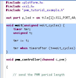
The function uses a timer to emit an event at some time in the future. Timers use the 100MHz reference clock to provide programmable delays to the software. The 100MHz clock gives 10ns resolution to these delays, allowing the software to precisely control the time at which actions occur. The logical core remains idle until that event happens, thereby saving power.
- Update the current pwm_controller function with the following code:
void pwm_controller(chanend c_pwm)
{
  // PWM period is 10us. 1000 cycles at 10ns (100MHz ref clock)
  int period = 1000;
  // duty_cycle starts at 100% which switches all LEDs off
  // (LEDs active low on GPIO sliceCARD)
  int duty_cycle = 1000;
  // duty cycle step (up or down)
  unsigned step = period / 100;
  // duty_cycle delta.
  int delta = -step; // start with increasing brightness

  // output the PWM period length to a channel
  c_pwm <: period;
  // output the PWM duty cycle length to a channel
  c_pwm <: duty_cycle;

  while(1) {
    // update the duty cycle length
    c_pwm <: duty_cycle;

    wait(XS1_TIMER_HZ/100); // 0.01 s
    duty_cycle += delta;
    if(duty_cycle > period) {
      delta = -step; // increase brightness
      duty_cycle = period;
    }
    else if(duty_cycle < 0) {
      delta = step; // decrease brightness
      duty_cycle = 0;
    }
  }
}
Show where the pwm_controller code goes
The new pwm_controller updates the PWM logical core, by periodically sending new PWM settings to it over the channel. There is a delay of 10ms between each update to the PWM core. The step between every successive duty cycle is 1/100 of a PWM period which means the time to go from 0 to 100% duty (LED fully on to LED fully off) is 100 * 10ms = 1 second.
- Click PWM in the Project Explorer and select Project > Build Project.
- Click Run.
The four LEDs are dimmed up and down every 2 seconds.
You can extend this simple example to any real-time task. Using the precise 100MHz timer, together with the deterministic execution of xCORE multicore microcontrollers makes it easy to accurately control your real-time tasks.
Add printing
The XTAG2 USB-JTAG converter and xTIMEcomposer provide a complete suite of development and debug tools including:
- debugger including breakpoints, watchpoints and single stepping.
- XScope real-time, in-circuit instrumentation that lets you view what’s going on in your code at run-time.
- JTAG I/O, allowing you to print from your application and view the output within xTIMEcomposer.
Using print statements over JTAG
- Add the following code at the top of main.xc to include the print library:
#include "print.h"
- Add a welcome message above the first channel communication in the pwm_controller() function using the printstr statement:
int delta = -step; // start with increasing brightness

printstr("Welcome to the XMOS PWM tutorial");

// output the PWM period length to a channel
c_pwm <: period;
Show where the printstr code goes
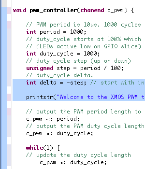
The print library includes functions for printing various different formats, including strings and integers.
- Build and run the application.
Your welcome message is printed to the xTIMEcomposer Console.
xTIMEcomposer Console
Add an I2C interface to read the temperature
The GPIO sliceCARD features an ADC that has a linearized thermistor connected for measuring temperature. The ADC is accessed via an I2C interface.
You can add an I2C Master interface using the xSOFTip I2C component to read the temperature, and use an interpolation function to convert the ADC value into a temperature, in the range -10 to 60 degrees C.
This section shows you how to:
- Read the ADC value periodically using the I2C master interface.
- Convert the ADC value into a temperature value.
- Print the temperature value.
Integrate the I2C interface
- Find the I2C Master (Single Bit Ports) xSOFTip in the xSOFTip Browser by typing I2C in the Search field. This I2C Master uses 1-bit ports for SCL and SDA.
- Find the Makefile inside your project in the Project Explorer.
As you are adding a module to an existing project, you need to add the module to the Makefile.
- Right-click on the Makefile and select Open With > Makefile Editor.
- Add module_i2c_master to USED_MODULES.
Your USED_MODULES will now be:
USED_MODULES = module_i2c_master module_pwm_tutorial_example
- Drag the I2C Master xSOFTip into the Project Explorer to add it to your project.
module_i2c_master is displayed in the project tree.
- Include i2c.h in your main.xc application file.
#include "i2c.h"
- Add the I2C ports to the top section of main.xc:
on tile[1] : struct r_i2c i2cOne = {
  XS1_PORT_1F,
  XS1_PORT_1B,
  1000
};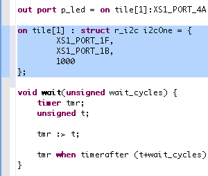
This declares a structure with two 1-bit ports which are the SCL and SCK pins for I2C. The third member of the structure is the speed of the bus. The I2C Programming Guide gives this description of the structure:
Structure Members
port scl - Port on which clock wire is attached. Must be on bit 0
port sda - Port on which data wire is attached. Must be on bit 0
unsigned int ``clockTicks`` - Number of reference clocks per I2C clock, set to 1000 for 100 kHz.
The location of the I2C ports can be found in the GPIO sliceCARD documentation.
Examine the I2C Master interface
The module supports multiple I2C Masters but you only need one Master (the xCORE) in this application.
The I2C component has a simple set of APIs to configure it, and to read and write data via I2C. These APIs execute functions which implement the I2C interface.
You will use the function i2c_master_write_reg to configure the ADC at startup. Using the tx8 function, it writes the Slave device ID, address and then a list of bytes.
- Open module_i2c_master/src/i2c-mm.xc.
- Find the i2c_master_write_reg function.
- Double click on the first instance of tx8 to mark it.
- Right-click on the marked tx8 and select Open Declaration.
The Editor window jumps to the tx8 function that implements the I2C protocol for writing a single byte.
The HighPulse() function sends each bit of the byte in a loop. The timing of the edges of the I2C SCL (clock) and I2C SDA (data) signals are controlled by the function waitQuarter which, like the wait function you implemented previously, uses a timer to emit an event in the future upon which the signal level is changed.
This is a basic example of a hardware interface implemented completely in software running on a logical core.
Using I2C in the PWM controller
This section shows how to modify the PWM controller function so that it reads the ADC via I2C every period of the LED cycle.
- Declare the variables you need above your printstr statement, and use the i2c_master_write_reg function to initialize the ADC.
// I2C write data
  unsigned char wr_data[1]={0x13};
  unsigned char rd_data[2];
  int adc_value;

  //Write configuration information to ADC
  i2c_master_write_reg(0x28, 0x00, wr_data, 1, i2cOne);

  printstr("Welcome to the XMOS PWM tutorial\n");
Show where the i2c_master_write_reg function goes

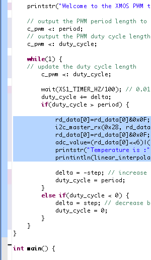
- Add the following code to use the I2C_master_rx function to read from the ADC at the end of the PWM cycle period. It should be inserted after the duty cycle is incremented (duty_cycle += delta;)
if (duty_cycle > period)
{
  //Read ADC value using I2C read

  rd_data[0]=rd_data[0]&0x0F;
  i2c_master_rx(0x28, rd_data, 2, i2cOne);
  rd_data[0]=rd_data[0]&0x0F;
  adc_value=(rd_data[0]<<6)|(rd_data[1]>>2);
  printstr("Temperature is :");
  printintln(linear_interpolation(adc_value));
Show where the i2c_master_rx code goes
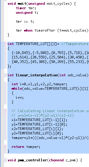
- Add the linear interpolation function above your pwm_controller. This function is used to convert the ADC value to a temperature value.
int TEMPERATURE_LUT[][2]= //Temperature Look up table
{
  {-10,845},{-5,808},{0,765},{5,718},{10,668},
  {15,614},{20,559},{25,504},{30,450},{35,399},
  {40,352},{45,308},{50,269},{55,233},{60,202}
};

int linear_interpolation(int adc_value)
{
  int i=0,x1,y1,x2,y2,temper;
  while(adc_value<TEMPERATURE_LUT[i][1])
  {
    i++;
  }
  // Calculating Linear interpolation using the formula
  // y=y1+(x-x1)*(y2-y1)/(x2-x1)
  x1=TEMPERATURE_LUT[i-1][1];
  y1=TEMPERATURE_LUT[i-1][0];
  x2=TEMPERATURE_LUT[i][1];
  y2=TEMPERATURE_LUT[i][0];
  temper=y1+(((adc_value-x1)*(y2-y1))/(x2-x1));

  return temper;
}
Show where the interpolation function goes
- Build and run your application.
Every two seconds the temperature is printed to your console. Check that the temperature is printed to your console.
Output temperature reading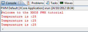
Next Steps
Congratulations! You have now used both the PWM and I2C xSOFTip, and used them to build and run a simple example. Both these interfaces are implemented in software, so you can view the code and make any changes you may wish to make. They rely on the deterministic, real-time capabilities of the xCORE architecture to deliver low latency, easy to use IP functions for use in your design.
We recommend that you:
- Browse xSOFTip and take a look at the other xSOFTip components. You can read through the documentation in the Developer Column, and use them in your project. XMOS and our partners are working on new xSOFTip components all the time. Some components you see here are Roadmap components which are in our development plan. If there is a component you require for your system, please let us know – we’d love to hear from you.
- Run the Example Applications for your sliceKIT Cards (look under sliceKIT in the xSOFTip Explorer). Each sliceKIT sliceCARD has its own Quick Start Guide to guide you through the demo application.
- Try some other tutorials: A range of tutorials are available covering the xTIMEcomposer tools, xSOFTip and xKIT development boards. See Help > Tutorials.
- Take a look at www.xmos.com/slicekit to view other sliceCARDs for use with your applications.