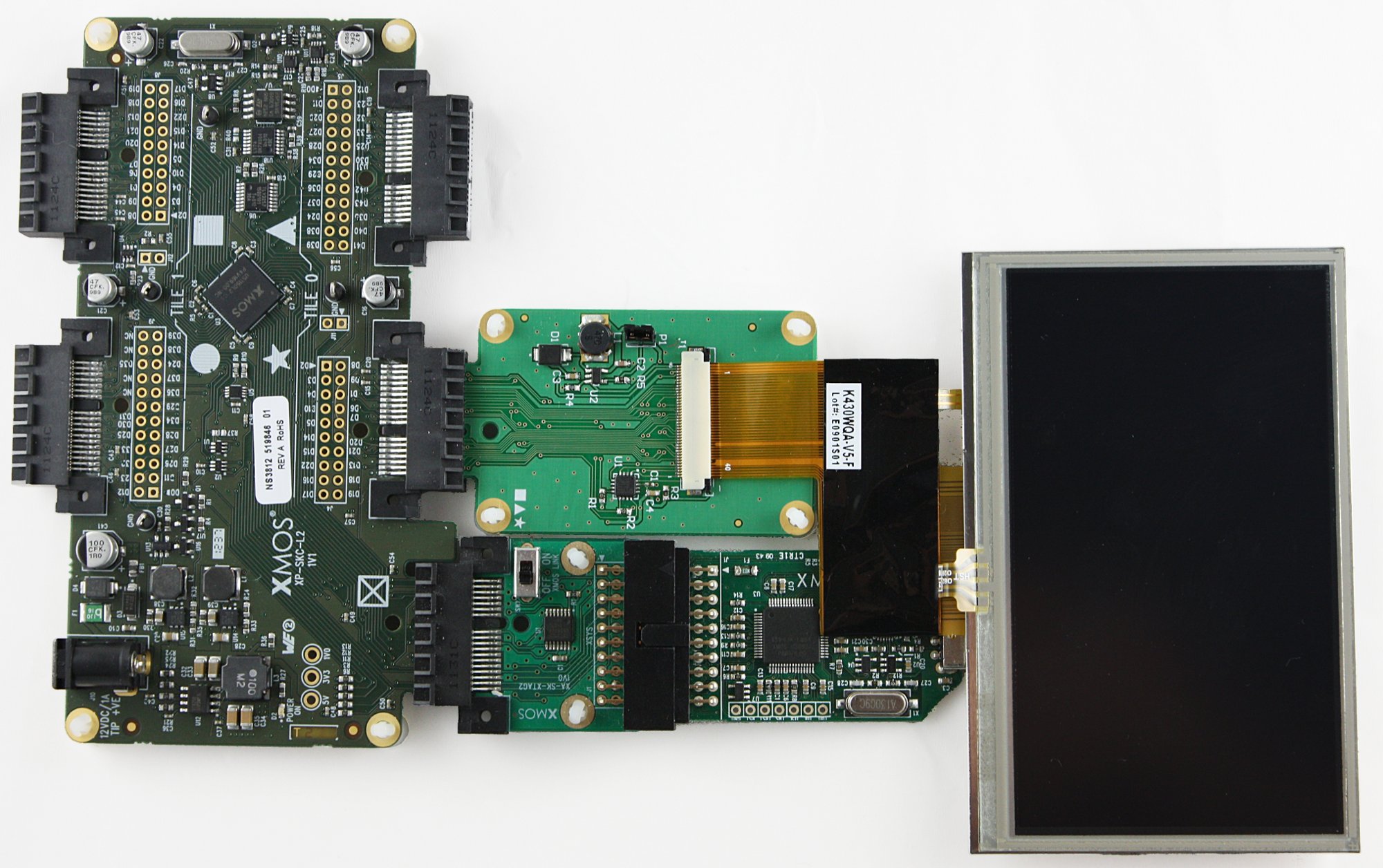
sc_lcd demo : Quick Start Guide
This simple demonstration of xTIMEcomposer Studio functionality uses the XA-SK-SCR480 Slice Card together with the xSOFTip module_lcd to demonstrate how the module is used to write to an LCD screen.
Hardware Setup
The XP-SKC-L2 Slicekit Core board has four slots with edge conectors: SQUARE, CIRCLE, TRIANGLE and STAR.
To setup up the system:
- Connect XA-SK-SCR480 Slice Card to the XP-SKC-L2 Slicekit Core board using the connector marked with the STAR.
- Connect the XTAG Adapter to Slicekit Core board, and connect XTAG-2 to the adapter.
- Connect the XTAG-2 to host PC. Note that the USB cable is not provided with the Slicekit starter kit.
- Set the XMOS LINK to OFF on the XTAG Adapter.
- Ensure the jumper on the XA-SK-SCR480 is bridged if the back light is required.
- Switch on the power supply to the Slicekit Core board.

Import and Build the Application
- Open xTIMEcomposer and check that it is operating in online mode. Open the edit perspective (Window->Open Perspective->XMOS Edit).
- Locate the 'Slicekit LCD Demo' item in the xSOFTip pane on the bottom left of the window and drag it into the Project Explorer window in the xTIMEcomposer. This will also cause the modules on which this application depends (in this case, module_lcd) to be imported as well.
- Click on the app_lcd_demo item in the Explorer pane then click on the build icon (hammer) in xTIMEcomposer. Check the console window to verify that the application has built successfully.
For help in using xTIMEcomposer, try the xTIMEcomposer tutorial. FIXME add link.
Note that the Developer Column in the xTIMEcomposer on the right hand side of your screen provides information on the xSOFTip components you are using. Select the module_lcd component in the Project Explorer, and you will see its description together with API documentation. Having done this, click the back icon until you return to this quickstart guide within the Developer Column.
Run the Application
Now that the application has been compiled, the next step is to run it on the Slicekit Core Board using the tools to load the application over JTAG (via the XTAG2 and Xtag Adaptor card) into the xCORE multicore microcontroller.
- Click on the Run icon (the white arrow in the green circle). The output produced should look like a bouncing “X” on the LCD screen.
Next Steps
- Trying changing the int x=20, y=0, vx=1, vy=2; variables, they represent: initial x coord, initial y coord, x velocity and y velocity respectivly.
- In the sub() function what would you expect to see if the line: buffer[i] = BACK_COLOUR; was changed to buffer[i] = 0x12345678;?
Look at the Code
- Examine the application code. In xTIMEcomposer navigate to the src directory under app_sdram_demo and double click on the app_sdram_demo.xc file within it. The file will open in the central editor window.
- Find the main function and note that it runs the demo() function on a single logical core.
Try the Full Display Controller Demo
These applications are necessarily limited since there is no external memory available for a proper framebuffer, and the internal memory of an XCore Tile is too small to buffer a full screen colour image. The Display Controller demo combines the functionality of this LCD module with the SDRAM Controller component and SDRAM Slice Card to implement a fully functioning LCD Display Controller by adding the memory controller and a component that takes care of framebuffer management.
Once you have both the XA-SK-SDRAM< and XA-SK-SCR480 slices you can try the Display Controller demo by