xTIMEcomposer Timing Tutorial
Introduction
The XMOS architecture has predictable timing, which allows many interfaces to be performed in software. This tutorial shows you how to add timing constraints to the parts of your program that must run within strict time limits, enabling correct real-time behavior to be validated for your target device at compile-time.
This tutorial shows you how to:
- Open a sample UART project in the xTIMEcomposer Studio Timing Perspective
- Validate the UART transmitter’s timing constraints interactively
- Validate the UART transmitter’s timing constraints during compilation
Open a project in the Timing Perspective
This part of the tutorial shows you how to create a project in xTIMEcomposer Studio and open it in the Timing view.
Create an application
Before writing any code, you need a project to store your files in. To create a project follow these steps:
- Choose
 to open the New xTIMEcomposer Project dialog.
 - In Project Name, enter a name such as timing.
- In Target Hardware, select the option XK-1A Board. You don’t need this board to complete the tutorial.
- In Application Software, select the option Empty XC File.
- Click Finish.
xTIMEcomposer Studio creates a new project containing an application. It then adds an empty source file to your application and opens it in the editor.

Add the code
The program below implements a UART interface:
/*
 * ==========================================================
 * Name        : uart-loopback.xc
 * Description : UART loopback example
 * ==========================================================
 */

#include <xs1.h>
#include <print.h>
#include <platform.h>

#define NUM_BYTES 3
#define BIT_RATE 115200
#define BIT_TIME XS1_TIMER_HZ / BIT_RATE

void txBytes(out port txd, char bytes[], int numBytes);
void txByte(out port txd, int byte);
void rxBytes(in port rxd, char bytes[], int numBytes);
char rxByte(in port rxd);


out port txd = XS1_PORT_1H;
in port rxd = XS1_PORT_1I;

int main()
{
  char transmit[] = { 0b00110101, 0b10101100, 0b11110001 };
  char receive[] = { 0, 0, 0 };

  // Drive port high (inactive) to begin
  txd <: 1;

  par {
    txBytes(txd, transmit, NUM_BYTES);
    rxBytes(rxd, receive, NUM_BYTES);
  }

  return 0;
}

void txBytes(out port txd, char bytes[], int numBytes)
{
  for (int i = 0; i < numBytes; i += 1) {
    txByte(txd, bytes[i]);
  }
  printstrln("txDone"); // Transmit_Done
}

void txByte(out port txd, int byte)
{
  unsigned time;

  // Output start bit
  txd <: 0 @ time; // Endpoint A

  // Output data bits
  for (int i = 0; i < 8; i++) {
    time += BIT_TIME;
    txd @ time <: >> byte; // Endpoint B
  }

  // Output stop bit
  time += BIT_TIME;
  txd @ time <: 1; // Endpoint C

  // Hold stop bit
  time += BIT_TIME;
  txd @ time <: 1; // Endpoint D
}

void rxBytes(in port rxd, char bytes[], int numBytes)
{
  for (int i = 0; i < numBytes; i += 1) {
    bytes[i] = rxByte(rxd);
  }

  printstrln("rxDone");
  for (int i = 0; i < NUM_BYTES; i++) {
    printhexln(bytes[i]);
  }
}

char rxByte(in port rxd)
{
  unsigned byte, time;

  // Wait for start bit
  rxd when pinseq (0) :> void @ time;
  time += BIT_TIME / 2;

  // Input data bits
  for (int i = 0; i < 8; i++) {
    time += BIT_TIME;
    rxd @ time :> >> byte;
  }

  // Input stop bit
  time += BIT_TIME;
  rxd @ time :> void;

  return (byte >> 24);
}
Copy and paste the code into your project, and then choose  to save your changes to file.
Examine the code
Take a look at the code in the editor.
The source code contains a transmitter thread and receiver thread running concurrently. The UART is configured to operate at a data rate of 115200 bits/s, and the transmitter outputs bytes of data as shown in the diagram below.

The quiescent state of the wire is high.
A byte is sent by first driving a start bit (0), followed by the eight data bits and finally a stop bit (1). A rate of 115200 bits/s means that each bit must be driven for a period of 1/115200 = 8.68us.
The transmitter source code has the following structure:
TX ->
TX-BYTE ->
  Output start bit     (Endpoint A)
  Loop-8
    Output data bit    (Endpoint B)
  Output stop bit      (Endpoint C)
  Wait for bit period  (Endpoint D)
When compiled and run on a target device, the time taken to execute the code between the following pairs of endpoints must always be less than 8.68us:
- Route 1: From Endpoint A to Endpoint B (from the start bit to data bit)
- Route 2: From Endpoint B to Endpoint B (between consecutive data bits)
- Route 3: From Endpoint B to Endpoint C (from the last data bit to the stop bit)
- Route 4: From Endpoint C to Endpoint D (holding the stop bit for the bit period)
- Route 5: Between successive calls to the function txByte
If the constraint on the fifth route is not met, individual bytes will be transmitted correctly, but the UART will operate at a lower data rate.
More generally, a route consists of the set of all paths through which control can flow between two endpoints. Each route has a worst-case time, in which branches always follow the path that takes the longest time to execute. This time must satisfy the constraint for the program to be guaranteed correct under all possible executions.
Validate timing constraints interactively
Before you can time your program, you need to compile it in Release mode. If you compile in Debug mode, the compiler will not optimize your program, and may produce conditional branches that are never executed at run-time. In this case you will need to manually exclude these paths from the timing analysis.
Compile the project in Release mode
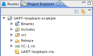
- Select your project in the Project Explorer.
- Click the arrow next to the Build button
 in the main toolbar
and select Release from the drop-down list.
 - Select the compiled binary in the Project Explorer in the subfolder bin/Release.
- Select
 to open your program in the Timing Perspective.
Validate Route 1
To check that the first route meets its timing constraint, follow these steps:
- In the editor, locate the first output statement (Endpoint A), right-click
on the endpoint marker in the left margin to bring up a menu, and choose
.
A green dot
 is displayed in the top-right quarter of the marker.
 - Locate the second output statement (Endpoint B), right-click on its endpoint
marker and choose .
A red dot is
 displayed in the bottom-right quarter of the marker.
 - Click the Analyze Endpoints button
 in the main toolbar.
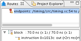
The timing analyzer identifies a single path between Endpoints A and B, which it times. The analyzed route is added to the Routes list in the top panel of the Routes view. The bottom panel of the Routes view shows a textual representation of the structure and timing for the selected route. The Structure panel in the Visualizations view shows a graphical visualization of the structure and timing for the selected route.
In the Routes list, a red question mark icon
 is displayed next
to the route name, indicating that no timing constraint is set.
- Right-click on the route in the Routes list to bring up a menu and choose to open the Requirement box.
- Enter a value of 8.68, select the unit us and click OK.
The red question mark is replaced by a green tick
 , indicating that
the route meets the specified timing constraint.
 - Hover over the route to view information such as the number of paths and worst-case timing.
Validate Route 2
To check that the second route meets its timing constraint, follow these steps:
- Right-click on the marker for Endpoint B to bring up a menu, and choose .
The warning triangle generated by the previous Analyze endpoints action obscures the endpoint marker, but you can still set a new endpoint by right-clicking on the marker.
This statement is now set as both the from and to endpoints
 .
. - Click Analyze Endpoints
 .
.The timing analyzer identifies the path around the loop. It also attempts to identify paths that exit the loop and then later re-enter it.
The lower panel of the Routes view shows the timing of the route is marked as unresolved, which means that some of the paths do not successfully reach the to endpoint. In this case the unresolved path ends at the exit system call and cannot therefore possibly re-enter the loop, which means it should be excluded from the analysis.
- Right-click on the first endpoint marker after the loop (Endpoint C) and choose .
All paths that pass through this marker are excluded, leaving only one path around the loop remaining in the route.
- In the Routes view, set a timing constraint of 8.68us.
The status of the route is updated, indicating that the route now meets its timing constraint.
Validate Routes 3 and 4
Use the techniques introduced in the previous two sections to check that Route 3 (Endpoint B to Endpoint C) and Route 4 (Endpoint C to Endpoint D) meet their timing constraints.
Once completed, a total of four routes should be displayed in the Routes list.
Validate Route 5
To check that route 5 meets its timing constraint (between consecutive byte transmissions), follow these steps:
- Set the endpoints for a route from Endpoint D to A.
- In the function txBytes, right-click on the endpoint marker
following the loop and choose .
The timing analyzer will not attempt to analyze paths outside of the loop.
- Click Analyze Endpoints
 in the main toolbar to create the route.
 - In the Routes view, set a timing constraint of 8.68us.
The status of the route is updated, indicating that the route meets its timing constraint.
You should have a total of five routes in the Routes list.
Validate the timing constraints during compilation
Having checked that all of the UART timing constraints are met, you can create a script that performs the same checks every time the program is compiled.
Generate a timing script
To create a timing script and update the source file with the pragmas required to make the script portable, follow these steps:
- Click Generate Script button
 in the main toolbar.
The Script Options dialog opens.
- Enter a name for the script (with a .xta extension) in the Script location text box.
- To change the names of the pragmas added to the source file, click the values in the Pragma name fields and edit.
- Click OK to save the script and update your source code.
xTIMEcomposer Studio adds the script to your project and opens it in the editor.

The next time you compile your program, the timing constraints are checked and any failures are reported as compilation errors.
What to read next
Congratulations you have finished this basic introduction the timing capabilities provided by the tools. For further information on using the XTA see the Timing Analyzer Manual.
For more information on using the xTIMEcomposer tools see the xTIMEcomposer User Guide.