System description
The following sections describe the system architecture of the XMOS AVB software platform.
This software design guide assumes the reader is familiar with the XC language and XMOS XS1 devices.
High level system architecture
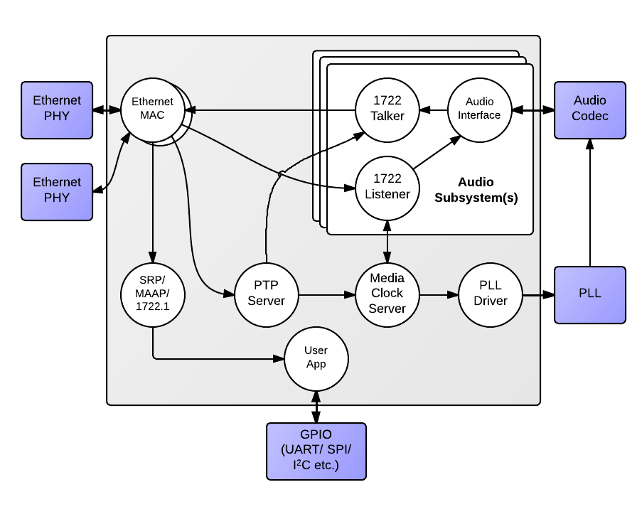
An endpoint consists of five main interacting components:
- The Ethernet MAC
- The Precision Timing Protocol (PTP) engine
- Audio streaming components
- The media clock server
- Configuration and other application components
The following diagram shows the overall structure of an XMOS AVB endpoint.
Ethernet MAC component
The MAC component provides Ethernet connectivity to the AVB solution. To use the component, a Ethernet PHY must be attached to the XCore ports via MII. The XS1 device is also capable of implementing a dual 100 Mbps interface - see the AVB Daisy Chain product for reference.
The XMOS Ethernet MAC component supports two features that are necessary to implement AVB standards with precise timing and quality constraints:
- Timestamping - allows receipt and transmission of Ethernet frames to be timestamped with respect to a clock (for example a 100 MHz reference clock can provide a resolution of 10 ns).
- Time sensitive traffic shaping - allows traffic bandwidth to be reserved and shaped on egress to provide a steady and guaranteed flow of outgoing media stream packets. The implementation provides flow control to satisfy the requirements of an AVB endpoint as specified in the IEEE 802.1Qav standard.
The single port 100 Mbps component consists of five logcial cores, each running at 50 MIPS or more, that must be run on the same tile. These logcial cores handle both the receipt and transmission of Ethernet frames. The MAC component can be linked via channels to other components/logcial cores in the system. Each link can set a filter to control which packets are conveyed to it via that channel.
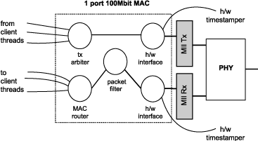
All configuration of the channel is managed by a client C/XC API, which configures and registers the filters. Details of the API used to configure MAC channels can be found in the Ethernet MAC component documentation. This API is used for direct (layer-2) access to the MAC. For AVB applications it is more likely that interaction with the Ethernet stack will be via the main AVB API (see Section AVB API).
1722 packet routing
The AVB enabled Ethernet MAC also includes a IEEE 1722 packet router that routes audio packets to the listener components in the system. It controls the routing by stream ID. This requires no configuration and is controlled implicitly via the AVB API described in Section AVB API.
Precision Timing Protocol component
The Precision Timing Protocol (PTP) component enables a system with a notion of global time on a network. The component implements the IEEE 802.1AS protocol. It allows synchronization of the presentation and playback rate of media streams across a network.

The timing component consists of two logcial cores. It connects to the Ethernet MAC component and provides channel ends for clients to query for timing information. The component interprets PTP packets from the MAC and maintains a notion of global time. The maintenance of global time requires no application interaction with the component.
The PTP component can be configured at runtime to be a potential PTP grandmaster or a PTP slave only. If the component is configured as a grandmaster, it supplies a clock source to the network. If the network has several grandmasters, the potential grandmasters negotiate between themselves to select a single grandmaster. Once a single grandmaster is selected, all units on the network synchronize a global time from this source and the other grandmasters stop providing timing information. Depending on the intermediate network, this synchronization can be to sub-microsecond level resolution.
Client tasks connect to the timing component via channels. The relationship between the local reference counter and global time is maintained across this channel, allowing a client to timestamp with a local timer very accurately and then convert it to global time, giving highly accurate global timestamps.
Client tasks can communicate with the server using the API described in Section PTP client API.
- The PTP system in the endpoint is self-configuring, it runs automatically and gives each endpoint an accurate notion of a global clock.
- The global clock is not the same as the audio word clock, although it can be used to derive it. An audio stream may be at a rate that is independent of the PTP clock but will contain timestamps that use the global PTP clock domain as a reference domain.
Audio components
AVB streams, channels, talkers and listeners
Audio is transported in streams of data, where each stream may have multiple channels. Endpoints producing streams are called Talkers and those receiving them are called Listeners. Each stream on the network has a unique 64-bit stream ID.
A single endpoint can be a Talker, a Listener or both. In general each endpoint will have a number of sinks with the capacity to receive a number of incoming streams and a number of sources with the capacity to transmit a number of streams.
Routing is done using layer 2 Ethernet addresses. Each stream is sent from a particular source MAC address to a particular destination MAC address. The destination MAC address is a multicast address so that several Listeners may receive it. In addition, AVB switches can reserve an end-to-end path with guaranteed bandwidth for a stream. This is done by the Talker endpoint advertising the stream to the switches and the Listener(s) registering to receive it. If sufficient bandwidth is not available, this registration will fail.
Streams carry their own presentation time, the time that samples are due to be output, allowing multiple Listeners that receive the same stream to output in sync.
- Streams are encoded using the 1722 AVB transport protocol.
- All channels in a stream must be synchronized to the same sample clock.
- All the channels in a stream must come from the same Talker.
- Routing of audio streams uses Ethernet layer 2 routing based on a multicast destination MAC address
- Routing of channels is done at the stream level. All channels within a stream must be routed to the same place. However, a stream can be multicast to several Listeners, each of which picks out different channels.
- A single end point can be both a Talker and Listener.
- Information such as stream ID and destination MAC address of a Talker stream should be communicated to Listeners via 1722.1. (see Section Device Discovery, Connection Management and Control).
Internal routing, media FIFOs
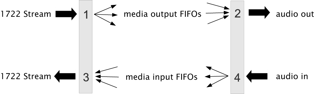
As described in the previous section, an IEEE 1722 audio stream may consist of many channels. These channels need to be routed to particular audio I/Os on the endpoint. To achieve maximum flexibility the XMOS design uses intermediate media FIFOs to route audio. Each FIFO contains a single channel of audio.
The above figure shows the breakdown of 1722 streams into local FIFOs. The figure shows four points where transitions to and from media FIFOs occur. For audio being received by an endpoint:
- When a 1722 stream is received, its channels are mapped to output media FIFOs. This mapping can be configured dynamically so that it can be changed at runtime by the configuration component.
- The digital hardware interface maps media FIFOs to audio outputs. This mapping is fixed and is configured statically in the software.
For audio being transmitted by an endpoint:
- The digital hardware interface maps digital audio inputs to local media FIFOs. This mapping is fixed and cannot be changed at runtime.
- Several input FIFOs can be combined into a 1722 stream. This mapping is dynamic.
The configuration of the mappings is handled through the API describe in AVB API.
Media FIFOs use shared memory to move data between tasks, thus the filling and emptying of the FIFO must be on the same tile.
Talker units
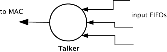
A talker unit consists of one logcial core which creates IEEE 1722 packets and passes the audio samples onto the MAC. Audio samples are passed to this component via input media FIFOs. Samples are pushed into this FIFO from a different task implementing the audio hardware interface. The Talker task removes the samples and combines them into IEEE 1722 Ethernet packets to be transmitted via the MAC component.
When the packets are created the timestamps are converted to the time domain of the global clock provided by the PTP component, and a fixed offset is added to the timestamps to provide the presentation time of the samples (i.e the time at which the sample should be played by a Listener).
A system may have several Talker units. However, since samples are passed via a shared memory interface a talker can only combine input FIFOs that are created on the same tile as the talker. The instantiating of talker units is performed via the API described in Section Component tasks and functions. Once the talker unit starts, it registers with the main control task and is controlled via the main AVB API described in Section AVB API.
Listener units
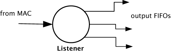
A Listener unit takes IEEE 1722 packets from the MAC and converts them into a sample stream to be fed into a media FIFO. Each audio Listener component can listen to several IEEE 1722 streams.
A system may have several Listener units. The instantiating of Listener units is performed via the API described in Section Component tasks and functions. Once the Listener unit starts, it registers with the main control task and is controlled via the main AVB API described in Section AVB API.
Media FIFOs to XC channels
Sometimes it is useful to convert the audio stream in a media FIFO into a sample stream over an XC channel. This may be needed to move samples off tile or if the audio interface task requires samples over a channel. Several functions are provided to do this and are described in Section Component tasks and functions.
Audio hardware interfaces
The audio hardware interface components drive external audio hardware, pull audio out of media output FIFOs and push into media input FIFOs.
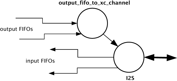
Different interfaces interact in different ways, some directly push and pull from the media FIFOs, whereas some for performance reasons require samples to be provided over an XC channel.
The following diagram shows one potential layout of the I2S component which pushes its input directly to media input FIFOs but takes output FIFOs from an XC channel. The diagram shows the supporting task that takes samples out of the media output FIFOs and serializes them over an XC channel:
Media clocks
A media clock controls the rate at which information is passed to an external media playing device. For example, an audio word clock that governs the rate at which samples should be passed to an audio CODEC. An XMOS AVB endpoint can keep track of several media clocks.
A media clock can be synchronized to one of two sources:
- An incoming clock signal on a port.
- The word clock of a remote endpoint, derived from an incoming IEEE 1722 audio stream.
A hardware interface can be tied to a particular media clock, allowing the media output from the XMOS device to be synchronized with other devices on the network.
All media clocks are maintained by the media clock server component. This component maintains the current state of all the media clocks in the system. It then periodically updates other components with clock change information to keep the system synchronized. The set of media clocks is determined by an array passed to the server at startup.
The media clock server component also receives information from the audio listener component to track timing information of incoming IEEE 1722 streams. It then sends control information back to ensure the listening component honors the presentation time of the incoming stream.
Multiple media clocks require multiple hardware PLLs. AVB-LC hardware supports a single media clock.
Driving an external clock generator
A high quality, low jitter master clock is often required to drive an audio CODEC and must be synchronized with an AVB media clock. The XS1 chip cannot provide this clock directly but can provide a lower frequency source for a frequency synthesizer chip or external PLL chip. The frequency synthesizer chip must be able to generate a high frequency clock based on a lower frequency signal, such as the Cirrus Logic CS2100-CP. The recommended configuration is as in the block diagram below:
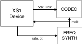
The XS1 device provides control to the frequency synthesizer and the frequency synthesizer provides the audio master clock to the CODEC and XS1 device. The sample bit and word clocks are then provided to the CODEC by the XS1 device.
Device Discovery, Connection Management and Control
The control task
In addition to components described in previous sections, an AVB endpoint application requires a task to control and configure the system. This control task varies across applications but the protocol to provide device discovery, connection management and control services has been standardised by the IEEE in 1722.1.
1722.1
The 1722.1 standard defines four independent steps that can be used to connect end stations that use 1722 streams to transport media across a LAN. The steps are:
- Discovery
- Enumeration
- Connection Management
- Control
These steps can be used together to form a system of end stations that interoperate with each other in a standards compliant way. The application that will use these individual steps is called a Controller and is the third member in the Talker, Listener and Controller device relationship.
A Controller may exist within a Talker, a Listener, or exist remotely within the network in a separate endpoint or general purpose computer.
The Controller can use the individual steps to find, connect and control entities on the network but it may choose to not use all of the steps if the Controller already knows some of the information (e.g. hard coded values assigned by user/hardware switch or values from previous session establishment) that can be gained in using the steps. The only required step is connection management because this is the step that establishes the bandwidth usage and reservations across the AVB network.
The four steps are broken down as follows:
- Discovery is the process of finding AVB endpoints on the LAN that have services that are useful to the other AVB endpoints on the network. The discovery process also covers the termination of the publication of those services on the network.
- Enumeration is the process of the collection of information from the AVB endpoint that could help an 1722.1 Controller to use the capabilities of the AVB endpoint. This information can be used for connection management.
- Connection management is the process of connecting or disconnecting one or more streams between two or more AVB endpoint.
- Control is the process of adjusting a parameter on the endpoint from another endpoint. There are a number of standard types of controls used in media devices like volume control, mute control and so on. A framework of basic commands allows the control process to be extended by the endpoint.
The XMOS endpoint provides full support for Talker and Listener 1722.1 services. It is expected that Controller software will be available on the network for handling connection management and control.
To assist in this task a unified control API is presented in Section AVB API.
Resource usage
Available chip resources
Each XMOS device has a set of resources detailed in the following table. The resources are split amongst different tiles on the device which may affect how resources can be used:
Device |
Logical Cores |
MIPS/Core |
Memory (KB) |
Ports |
|---|---|---|---|---|
XS1-L16A-128-QF124-C10 |
16 |
1000 |
128 |
32 x 1bit
12 x 4bit
7 x 8bit
3 x 16bit
|
Note that some ports overlap on the device so, for example, using a 16 bit port may make some 1 bit ports unavailable. See the device datasheets for details.
The following sections detail the resource required for each component. Please note that the memory requirements for code size should be taken as a rough guide since exact memory usage depends on the integration of components (which components are on which tile etc.) in the final build of the application.
Ethernet component
Each endpoint requires an Ethernet MAC layer.
Component |
Logical Cores |
MIPS/Core |
Memory (KB) |
Ports |
|---|---|---|---|---|
Ethernet |
5 |
50 |
15 code, 1.5 per buffer |
6 x 1bit, 2 x 4bit |
PTP component
Every AVB endpoint must include a PTP component.
Component |
Logical Cores |
MIPS/Core |
Memory (KB) |
Ports |
|---|---|---|---|---|
PTP |
1 |
50 |
7 |
None |
Media clock server
Every AVB endpoint must include a media clock server.
Component |
Logical Cores |
MIPS/Core |
Memory (KB) |
Ports |
|---|---|---|---|---|
Media Clock Server |
1 |
50 |
1 |
None |
If the endpoint drives an external PLL, a PLL driver component is required.
Component |
Logical Cores |
MIPS/Core |
Memory (KB) |
Ports |
|---|---|---|---|---|
PLL driver |
0 - 1 |
50 |
0.5 |
1 x 1bit + ports to configure PLL |
PTP, Media Clock Server and PLL driver components may be combined into a single logical core running at 100 MIPS if the number of channels is constrained to 2.
Audio component(s)
Each endpoint may have several listener and talker components. Each listener/talker component is capable of handling four IEEE 1722 streams and up to 12 channels of audio.
Component |
Logical Cores |
MIPS/Core |
Memory (KB) |
Ports |
|---|---|---|---|---|
1722 listener unit |
1 |
50 |
5 |
None |
1722 talker unit |
1 |
50 |
5 |
None |
The Talker and Listener components may be combined into a single logical core running at 100 MIPS if the number of streams is 1 and the number of channels is <= 4.
The amount of resource required for audio processing depends on the interface and the number of audio channels required. The overheads for the interface are:
Component |
Logical Cores |
MIPS/Core |
Memory(KB) |
Ports |
|---|---|---|---|---|
I2S |
1 |
50 |
0.5 |
3 x 1bit
1 x 1bit per stereo channel
|
The following table shows that number of channels an interface can handle per logical core:
Component |
Sample Rate (kHz) |
Channels |
|---|---|---|
I2S |
44.1/48 |
8 in and 8 out |
I2S |
88.2/96 |
4 in and 4 out |
Note that several instances of the audio interface component can be made e.g. you could use 2 logical cores to handle 16 channels of I2S. The following table shows how much buffering memory is required depending on the number of audio channels.
Sample Rate (kHz) |
Audio Channels |
Memory (KB) |
|---|---|---|
44.1 |
n in/m out |
0.5 x (m) |
48 |
n in/m out |
0.5 x (m) |
88.2 |
n in/m out |
1 x (m) |
96 |
n in/m out |
1 x (m) |
Configuration/control
In addition to the other components there are application dependant tasks that control other I/O. For general configuration and slow I/O a minimum of 1 logical core (50 MIPS) should be reserved.